1. Building the PCB
MIDI Madness Maker V1
Congratulations with your MIDI Madness Maker DIY kit! Let’s get it up and running. Follow the steps below for a successful build.

If you have never soldered before, and want to know the basics, we can recommend to take a look at the Adafruit Guide To Excellent Soldering.

Step 1. Check your DIY Kit
Bill of Materials
Make sure your kit comes with the following components:
- 1x PCB MIDI Madness Maker
- 1x ESP32S3
- 2x Female pin headers
- 1x Bluetooth Antenna (rectangle component with wire attached)
- 4x Resistors
- 1x Voltage Regulator L780SCV
- 1x 100kΩ potentiometer
- 1x Audio jack Thonkiconn type
- 1x Audio jack flat pcb type
- 1x Power barrel jack
- 1x 8Ω speaker
- 1x Slide switch
- 1x LED

(in this overview, pretend that the diode is a voltage regulator and imagine there also being 2x female pin headers).
Step 2. Building the DIY Kit
Instructions
Now that we know everything is complete in our DIY kit, we can start with soldering the components. For this we recommend putting components in the board one by one and by type, instead of all at once before soldering. This prevents the board from getting overcrowded. When soldering DIY Kits, we start with the smallest components first.
Follow the instructions below together with the interactive BOM (Bill Of Materials), so you can find the location of where to put the components on the PCB:
https://v0ss3n.github.io/midimadness/midimadnessmaker-ibom.html
Please note that D1 has been replaced with a voltage regulator. More on that later!
Resistors
In your kit you find 4 different types of resistors, they are colour coded with bands to show what value the resistor is. Make sure you place the correct value on the correct spot. Resistors don’t have a polarity, so they don’t have a ‘direction’ and orientation doesn’t matter.
- R4: 1 x 470Ω (Brown - Black - Black - Purple - Gold)
- R1: 1 x 100Ω (Brown - Black - Black - Black - Brown)
- R2 + R3: 2 x 47Ω (Brown - Gold - Black - Purple - Yellow)

LED
Next we solder in the LED. Be mindful of the polarity of the LED! The negative side (SHORT LEG) needs to be inserted in the SQUARE PAD! The long side of the LED will be in the round pad. Here, orientation matters.

Pin Headers
The pin headers are there to keep the ESP32 in place so you can take the microcontroller in and out if needed. If you want to make sure the pin headers are not wiggling, plug the ESP32S3 into the headers before soldering. That way the pin headers will be parallel.

Switch
Solder the switch in the location of the PCB, wiggle the switch a bit back and forth to place it inside the holes of the pcb. It’s a tight fit :)

Audio and MIDI Jack
In the kit you find 2 audio jacks:
- MIDI_TR_S1: Audio jack (flat type) for MIDI output
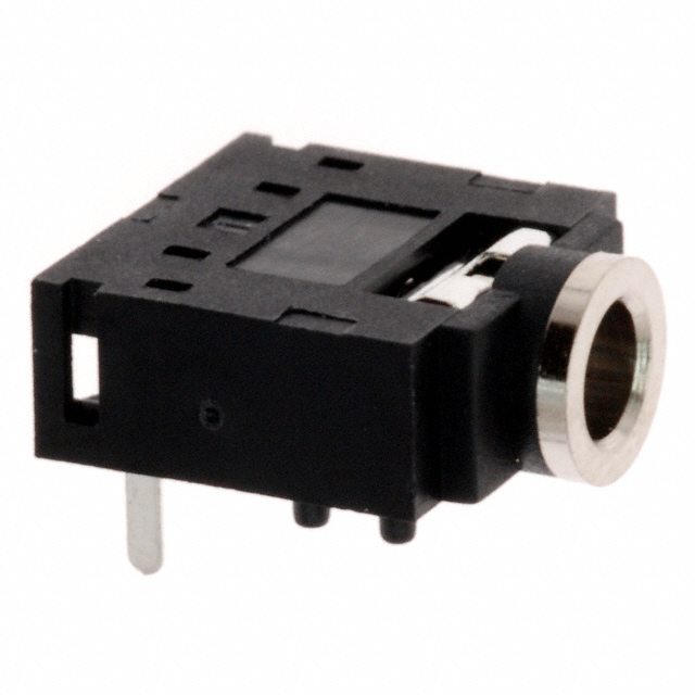
- Speaker_in1: Audio output jack (thonkiconn type) for audio output

The footprint on the board will tell you which one goes where.
Potentiometer
Solder the potentiometer (knob) at the location where the pcb shows the text “E_textile_tuner_1” If the potentiometer is struggling to fit in the holes bend them over a bit with your hands to make it fit in the spot. Solder all the pads (also the potentiometer mounting pads).

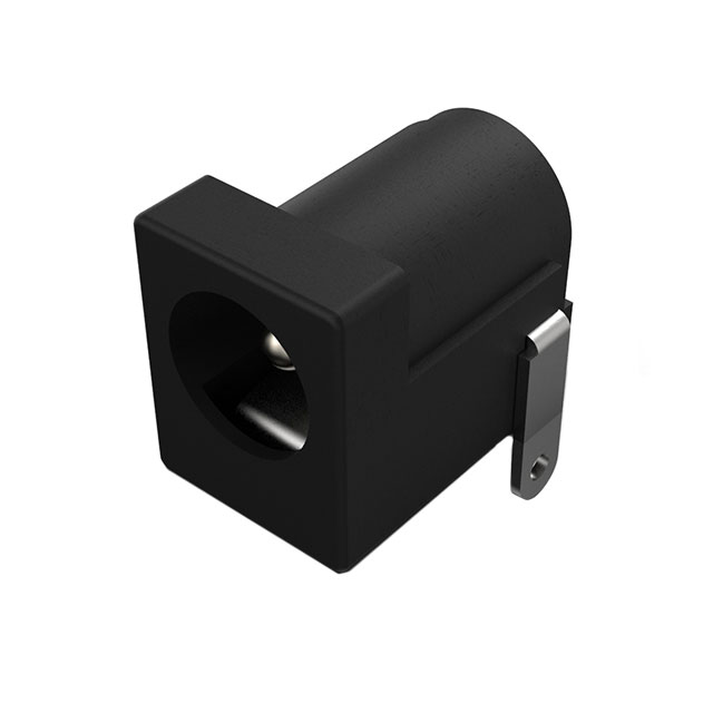
Power Barrel Jack
The barrel jack is used for powering the kit via external power sources that are not USB. You can use a 9V battery to power the kit externally. Only power it externally when you’re not plugged in with USB cable! Because the voltage regulator replaces the diode, there is no longer a component forcing the correct direction of current.
Voltage Regulator
The Voltage Regulator is a later addition to the first iteration of the DIY kit, because we wanted to power the board via 9V battery. Our microcontroller is only able to handle 5V maximum, so therefore we use the Voltage Regulator to step down the 9V to 5V.

The voltage regulator is type L780SCV and we place it on the location where the diode was supposed to be soldered in on location D1. Position the regulator with the flat side towards the microcontroller. The outer two legs should now be soldered each in a round pad on the PCB, and the middle leg of the regulator is soldered to the outside of the potentiometer next to it.

Now, you need to do some hacking: we need to create a little bridge between the side of the potentiometer mounting pad where we soldered the middle leg to, and the ground pin of the potentiometer. We can do this on the other side of the PCB. The connection you need to make is indicated with red in the image below. Use a piece of resistor leg that you cut off for this.

Speaker and Bluetooth Antenna
Solder the speaker to the pads on the PCB, the black wire is connected to the square pad, the red wire to the circular pad. Strip the wires so they’re easier to solder. You can stick the speaker to the front or back side of the MIDI Madness Maker.

The Bluetooth antenna can be added later when using Bluetooth functions. The ESP32 Bluetooth is already onboard but the antenna amplifies the signal so you can have more distance between source and receiver. You can clip it to the ESP32 as is done in the image below.

ESP32 Microcontroller
The ESP32S3’s orientation is important: the USB-C port should face away from the pcb board.
DONE!
Do not power the DIY kit just yet! Check the bottom of your pcb for any blobs of solder that could use a bit more love, make sure solder points that should not be connected, are not accidentally connected, and if any clips or components leads might be touching each other or sticking out make sure to trim them.

Step 3. Testing the DIY kit
Power
Before we test our DIY kit, make sure that you ONLY power the kit via one of the power options! Either use the USB connector on the ESP32, OR use the external 9V power supply option, not both at the same time!
When the microcontroller is in the board, connect the usb-c cable and power the kit using a usb block or your computer. The LED on the ESP32 should blink or be lit to indicate the board is powered.
Power options for the MIDI MADNESS MAKER
-
Power over USB (5V) directly on the ESP32. This is the easiest option, connect a USB-C cable from the microcontroller to your laptop or USB power block
-
Power over 9V battery using the external DC Barrel jack Connector You can use a 9V battery or 9V adapter to power the MIDI madness maker on the bottom side, this is not recommended to do during prototyping though, the regulator get’s warm when used and using a power block is not as safe as over USB for prototyping. You can use these methods, when you have stabilized your setup and you are looking for ways to power externally that are not over USB.

- Power over USB using an external powerbank. You can use a powerbank to power the MIDI Madness Maker! This is a great option for when you want to implement the kit into a garment or object and you don’t like to work with single use batteries.
END OF THE BUILD GUIDE
-> Go to the “SOFTWARE SETUP” page on this website, to upload your first code onto the board!