Hardware & software
You can already make electronic wearables without a microcontroller. For example, you can use a coin cell battery (and optional coin cell battery holder with on/off switch) and an LED or LED filament and make something that emits light. You can even make it interactive by introducing an LDR (light dependent resistor) to the mix. But once you start using a microcontroller and programming, the sky is the limit!
Kit
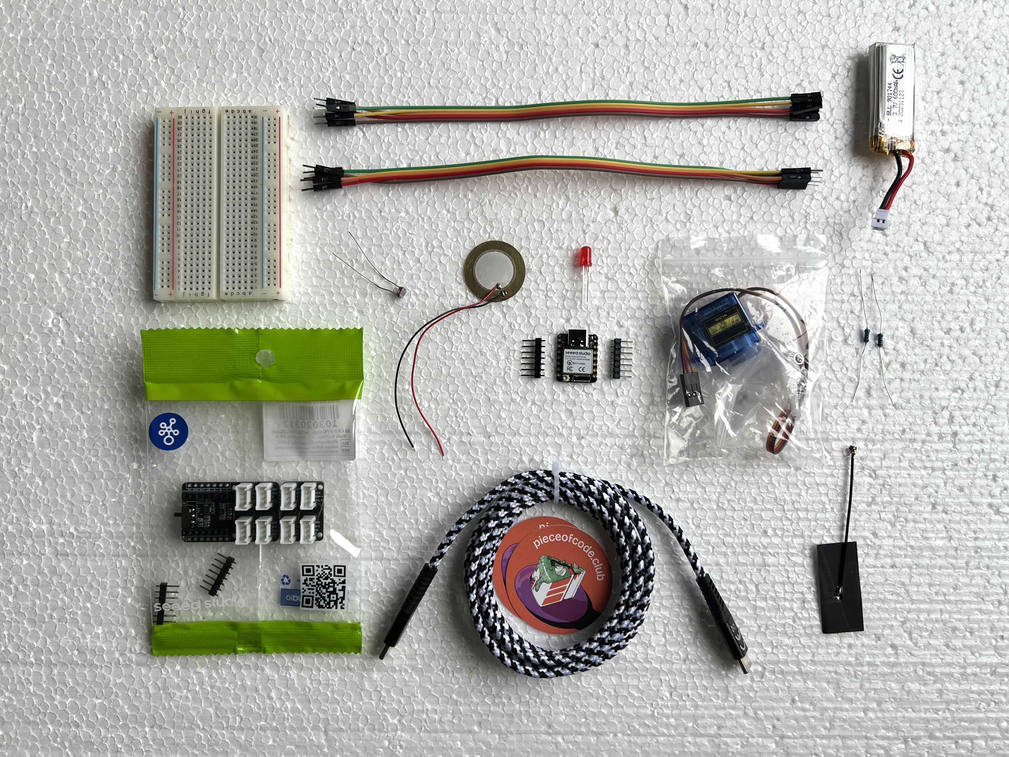
You all received a kit with the following content:
- Seeed Studio XIAO ESP32S3 development board + 2 sets of header pins + Bluetooth antenna
- Grove Shield for XIAO with battery management chip
- Breadboard
- Jumper wires (male/male & male/female)
- Lithium ion battery (3.7V 600mAh)
- USB-C to USB-C or USB-A cable
- LED
- LDR
- 2 resistors: 67 Ohm and 4.7k Ohm
- Micro servo motor
- Piezo buzzer
Check if the content of your kit matches the picture below (approximately):
Soldering
Here is a soldering comic adaptation by Andie Nordgren that shows you the basics of soldering:

And here another reference image:

We are going to bring this to action with the header pins of the XIAO board, so we can easily prototype electronic circuits:
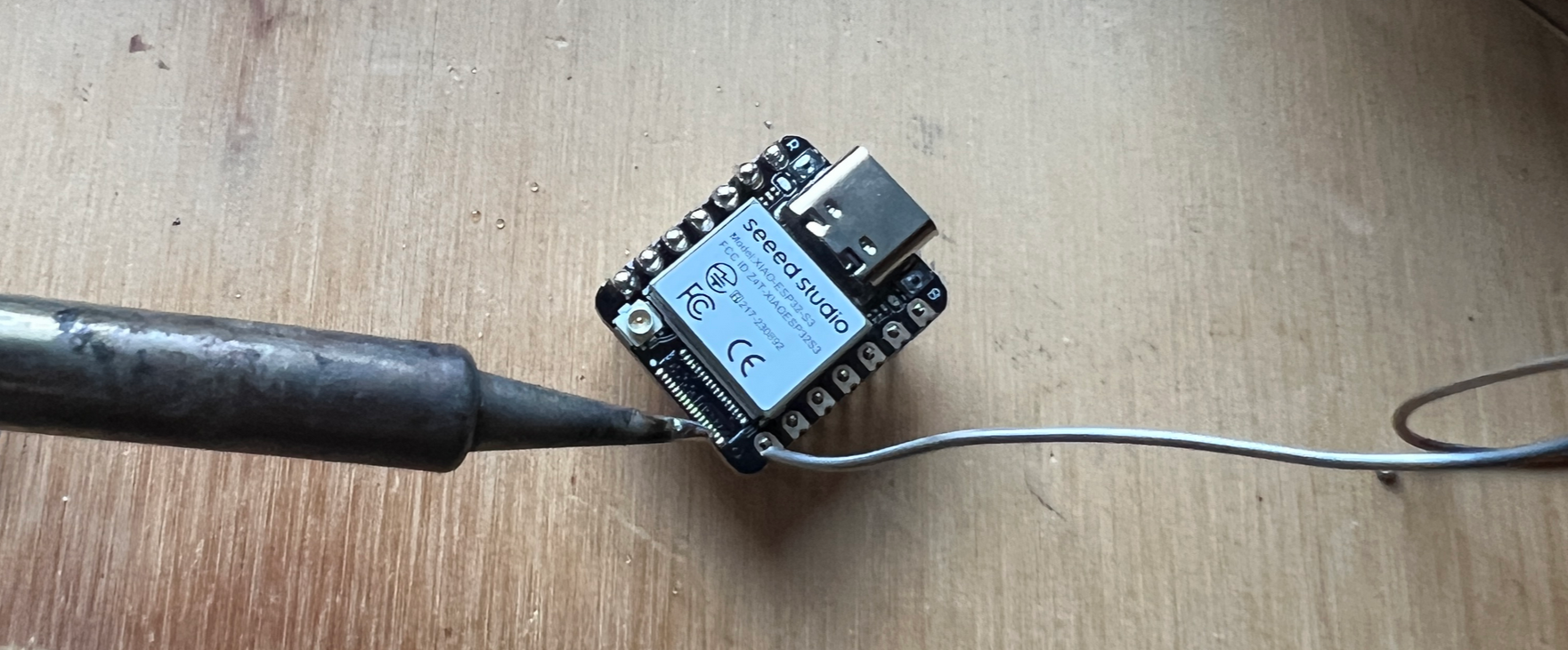
When soldering wires, make sure your connections are strong.

You could for example make a flexible LDR voltage divider like this:
Setting up the Arduino IDE
In these examples we’re using a Seeed Studio XIAO ESP32S3. Their wiki is a great place to get started and acquainted with all of the possibilities this tiny development board has to offer. But first, we need to install some drivers. For both Mac and Windows, you can get them here (CP210x VCP Mac OSX Driver or CP210x Windows Drivers). For Mac, it can also work to just follow the steps below and then upload something to your ESP32 for the first time; there should be a prompt to install some drivers at some point.

For a quick start, follow these steps in the Arduino IDE (assuming you have it installed already; if not, download the latest stable version and launch it):
- Navigate to
File > Preferences, and paste this URL in the ‘Additional Boards Manager URLs’: https://raw.githubusercontent.com/espressif/arduino-esp32/gh-pages/package_esp32_index.json - Now, navigate to
Tools > Board > Boards Manager..., type the keyword “esp32” in the search box, select 2.0.17 (the latest version, 3.x.x, does not work with the ESP32Servo library) and install it. - Plug in your board and select the board and port from the dropdown menu in the top left of the interface. Click on ‘Select other board and port’ and look for the XIAO_ESP32S3.
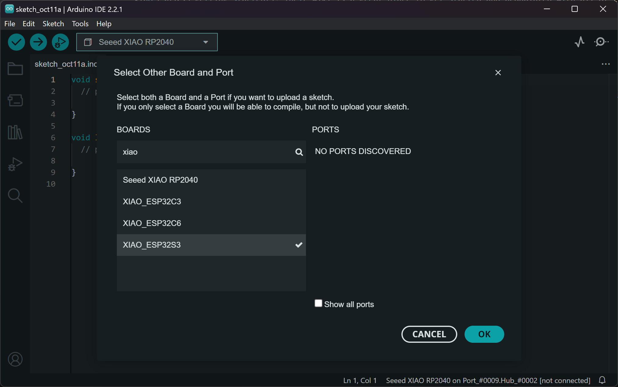
That should be it! Now you can start uploading the example code or write your own. One thing to keep in mind with ESP32s is that sometimes they’re in the wrong mode for programming. You can get back to boot mode by unplugging the board, then pressing and holding down the boot button on the board, then plugging it back in. Now it should work again :-)
Basic setup
To prototype wearables, we’re going to use the Grove Shield for XIAO, which makes trying things out very easy. You can even charge your LiPO battery with the XIAO while it’s on the shield, so you don’t need a separate charger for it. It’s plug and play and you can snap off the smaller part of the base if you don’t need it. It snaps off easily:
You can always leave out the shield if it’s too bulky for your final wearable once you know how you want to wire everything. There is also protoboard available if you prefer to solder it all together.

To start out, we’ll use the shield as a prototyping board together with a breadboard. You can plug Grove cables into the sockets to connect the data pins to your inputs and outputs, you can solder wires to the GPIO holes or you can solder sockets into the GPIO holes (like below) to plug in jumper wires to plug & play!
You can also just use the mini breadboard to start prototyping with, and leave the shield for later!
Battery use
Please pay careful attention when plugging in the battery into the development shield: connect + to + and - to minus!
The battery is about the same size as the shield, so you could fold it like this and use velcro or double sided tape to stick them together. I wouldn’t use glue since I’m not sure how it would react with the battery and the shield.
I would cover the bottom of the board with tape to avoid making any short circuits, for example if you want to glue a metal clip to the base to make it wearable.
Resistors
For the LEDs, we are using a 67 Ohm current limiting resistor. The values for the resistor in series with an LED depend on a couple of factors (color, power supply voltage, current rating); 67 Ohm is based on a power supply voltage of 3.3V, an average voltage drop of 2V and a current rating of the LED of 20 mA. There’s calculators for this online :-) If you use a bigger value resistor, it will still work, but the LED will shine a little less bright. If you use a smaller value resistor, the LED may shine a bit brighter, but it could also break in the long term (theoretically).
For the LDR there is a 4.7k Ohm resistor in your kit. I chose this value because it works well with the LDRs as they have a similar range. If you buy your own LDRs they may have different min and max values so try it out or check the datasheet.
Arduino code & circuits
Example code can be found in the Arduino (code) folder. You can find examples on programmed and external, digital, analog and touch input, combined with light, motion or sound output. Below you can find how you should wire up the circuits on a breadboard. This is also described in the Arduino code files. Find out how they work in the Arduino code files too!
Programmed input
- Blinking an LED (light output, digitalWrite)
- Fading an LED (analogWrite, PWM)
Wire up your circuit on the breadboard like this:
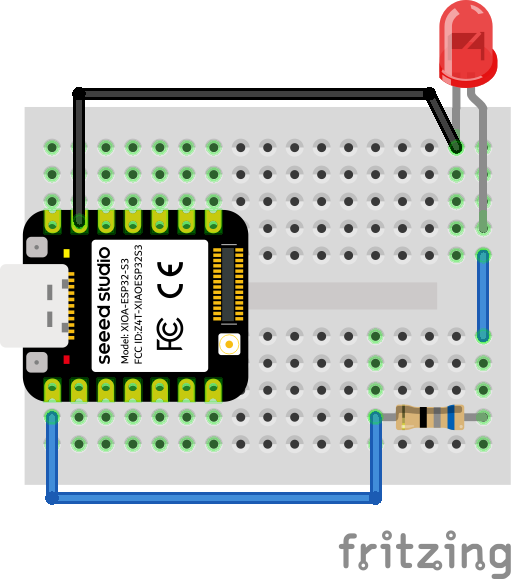
Here is a video of what the output should be.
If you connect the LED to an ESP32S3 on a Grove shield, the result is the same:
Digital input
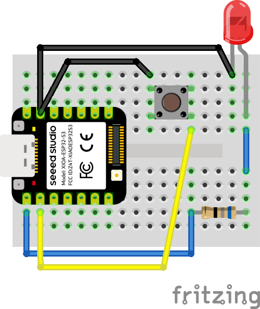
- Using a momentary push button to turn on an LED (digitalRead, using internal pullup resistor)
Wire up your circuit like below.
Analog input
- Reading LDR sensor data (serial monitor)
- Using LDR sensor data to fade LED (mapping input values to output values)
- Using LDR sensor data to light up Neopixels (libraries)
For the LDR & LED examples, set up your circuit like below.
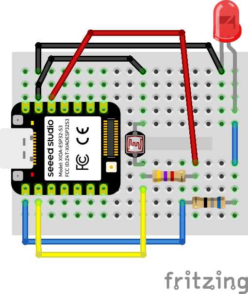
Here you can see the expected interaction:
And for the Neopixel strip, wire it up like this:
![]()
Also an example when the ESP32S3 is on the Grove shield:
![]()
- Sweeping a servo with LDR input (motion output)
Wire up like this:
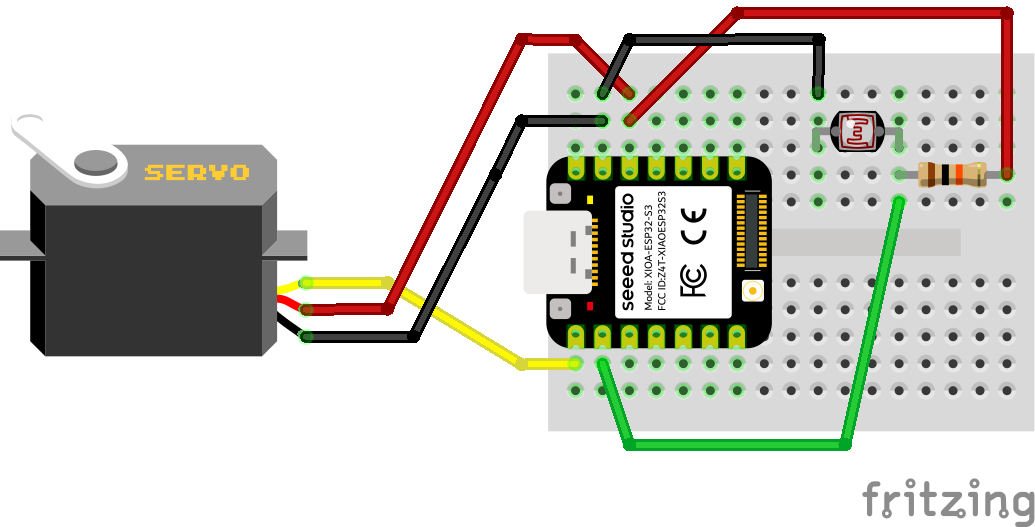
As a wearable, this is what you can do with a servo motor and an LDR!
If you’ve made the circuit with an LDR, it’s only one step further to connect your own, self made sensor! Take out the LDR, and stick two jumper wires to alligator clip in where the LDR legs were.
Touch input
- Turning on an LED with touch (touchRead, using input to do something with output, while statement)
- Toggling an LED with touch (if/else statement)
- Fading an LED with touch (touchRead, mapping capacitance ranges)
- Mapping a capacitance range to tones on a speaker (sound output, tone)
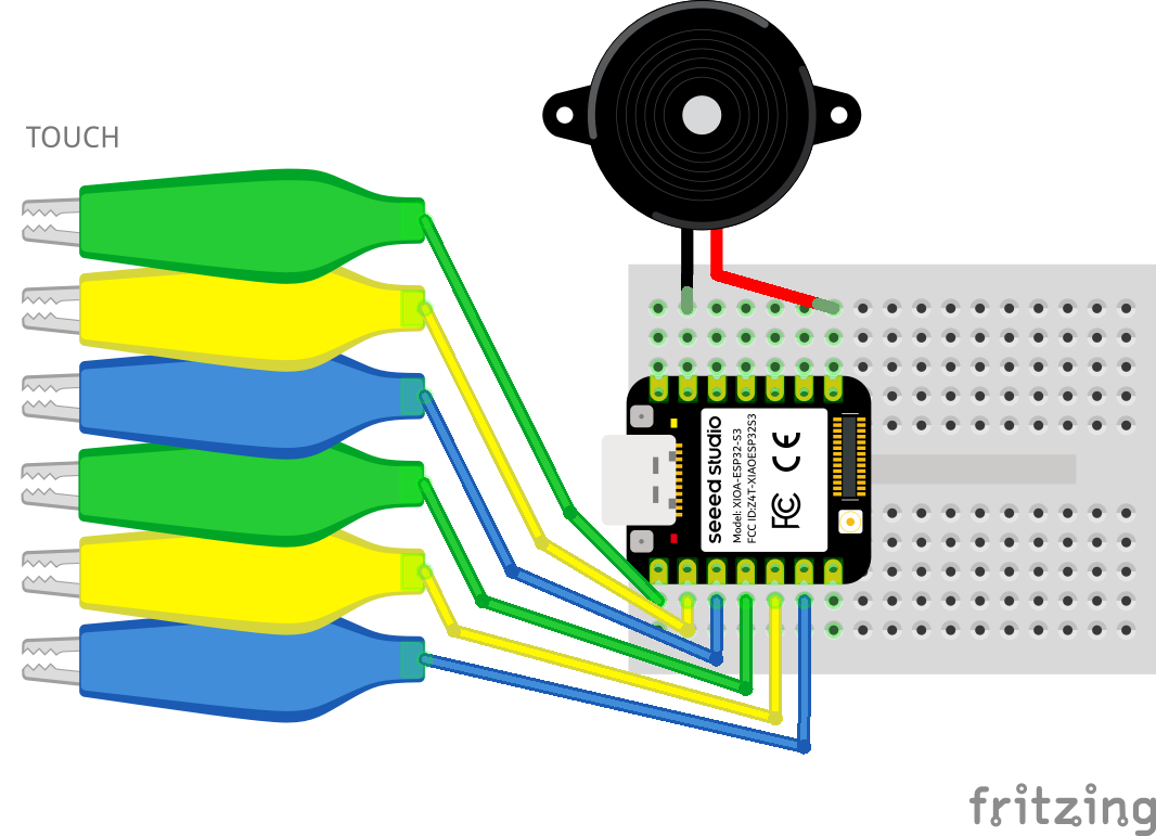
- Using touch pins to make a keyboard (multiple pins, arrays)
For the touch & LED examples, wire up the breadboard like below. The alligator clip can also be a male/male jumper wire, as long as there is something that you can touch.
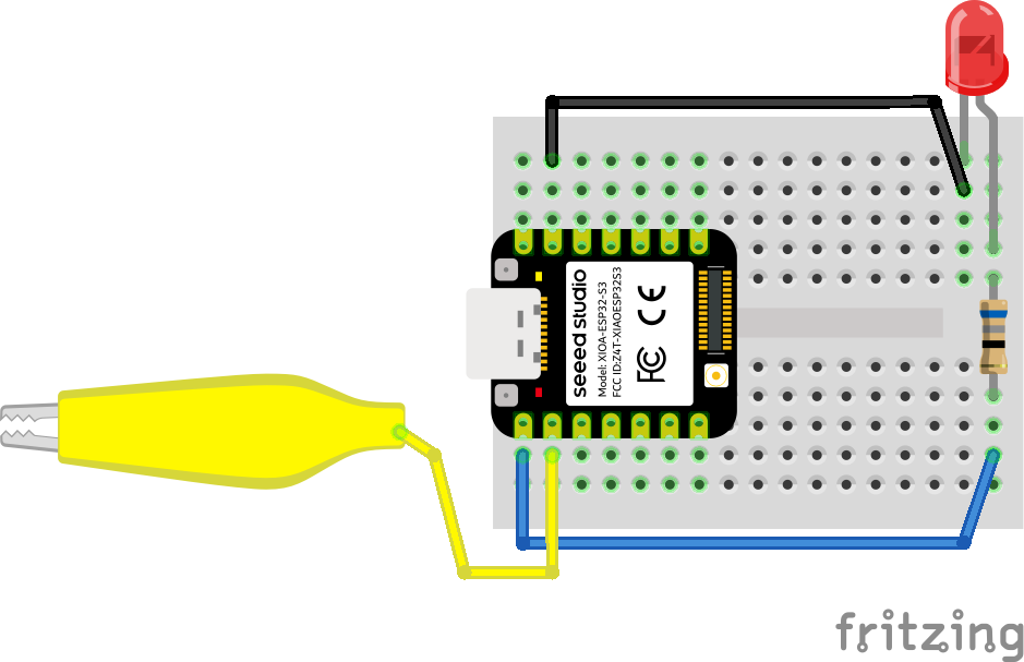
Here a jumper wire is used; when you touch the end of the wire, the LED lights up.
The touch & speaker examples can be wired up like below; in this example it’s with a buzzer but it also works with a piezo buzzer like in the kit!
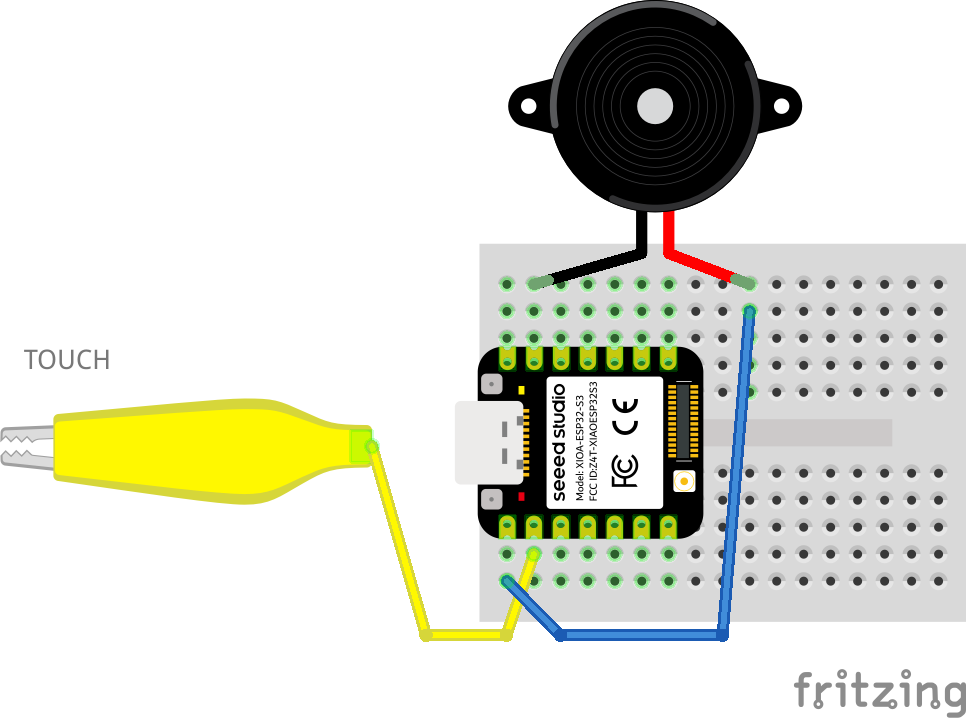
The touch range example sounds like this:
You can also connect something conductive, like a conductive spool knitted sample. Now the interaction is way more interesting!
And if you want more touch sensors, just plug in more wires in the touch pins you want to use. I moved the speaker to the other side now so all touch inputs are on one side.
