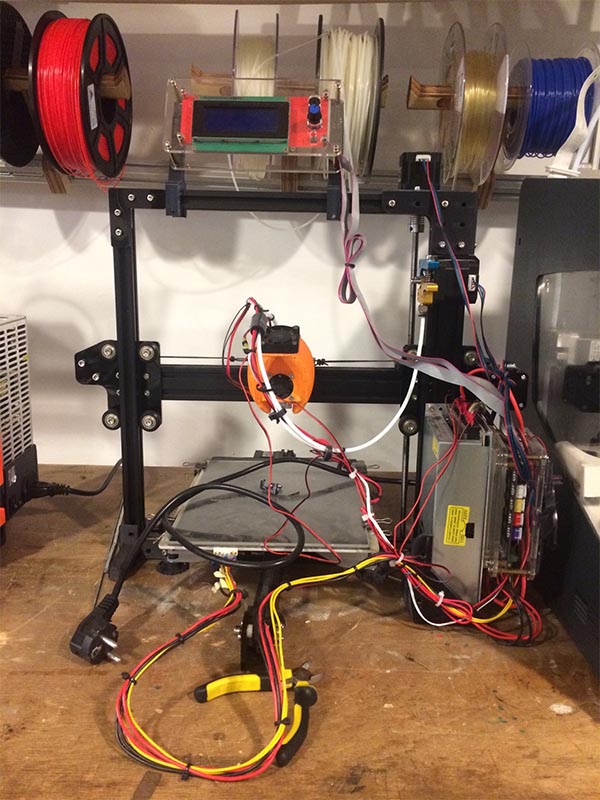
Tevo Tarantula
Some issues
- The bed is not completely level and secure (moves easily)
- Homing the X-axis stopped working
- Stringing: I tried lowering the nozzle temperature from 215 to 200, but the oozing seemed to be the same
- Flexible filament cannot be used as the filament gets stuck in the filament extruder
The Tevo Tarantula at the fablab works, but since the bed is not very secure (prone to shake easily) the end result is always a suprise (usually a bad one). The first test I did worked fine until the roll of PLA got stuck, the material broke and the printer started printing in the air. The only noticeable issue was that on one side of the print the resolution was slightly lower, probably because the bed was tilted slightly towards the back.
Endstop troubleshooting
On friday when I tried to home (move to 0) the X-axis, the printer did not seem to notice the endstop: it tried continuing and then the machine halted. The printer did not want to print after that. The stepper motor did not stop when reaching the endstop, for which the most probable cause is a bad endstop or a bad connection.
As the bed apparently already moved around too much and I cannot level the bed without encountering the endstop issue again, I first updated the firmware. I used this tutorial and downloaded the firmware from https://github.com/JimBrown/MarlinTarantula. However the issue was not resolved with this.
On monday homing the axes separately suddenly went fine, so I thought it was just a little hiccup and the endstops or cables were OK. However when trying to level the machine after homing the three axes, the same problem as on friday occured. What I found on reddit was to try to manually trigger the endstop before it got to the end, and after that it continued to the end and then stopped like it was supposed to. That is only a temporary solution though.
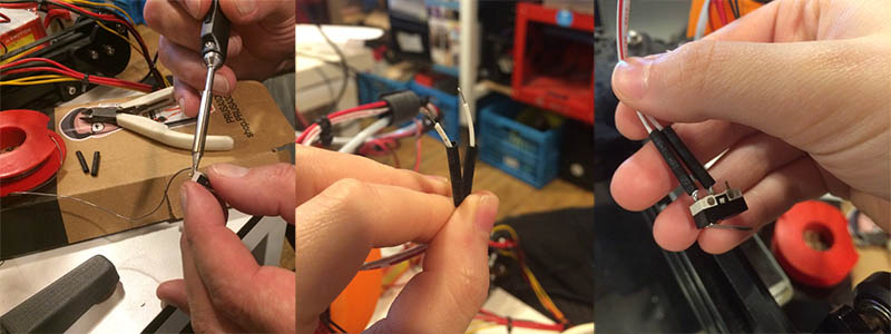
Updating the firmware had no influence on the bed leveling function working again and after testing the X-axis endstop with a multimeter we determined it was not soldered properly and had to be resoldered. After this, bed leveling worked. So it ended up being an issue with the endstop anyway, it just worked sometimes when the cables were accidentally touching.
First test: printing a button
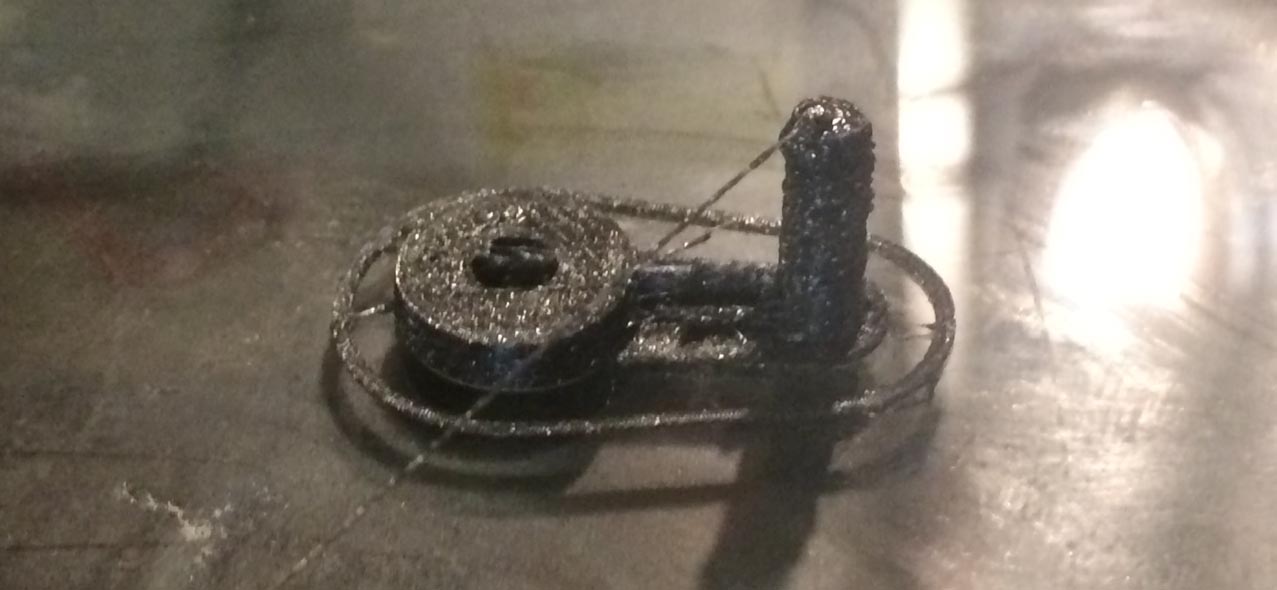
As a test print, I printed a little reset button I found online (https://www.thingiverse.com/thing:2153231/). The settings I used were the standard PLA settings on the Tevo Tarantula (275°C nozzle, 90°C bed). The temperature of the bed seemed to be too hot as the bottom of the print was very flat. The part that is sticking out to press the button did not look very nice either, it looked as if the nozzle was too hot too. Looking at the recommended settings on the spool of PLA, it says 205-225°C for the nozzle and 40-60°C for the bed, so for the next test something in this range should be better. Below the results of the first test.
Second test
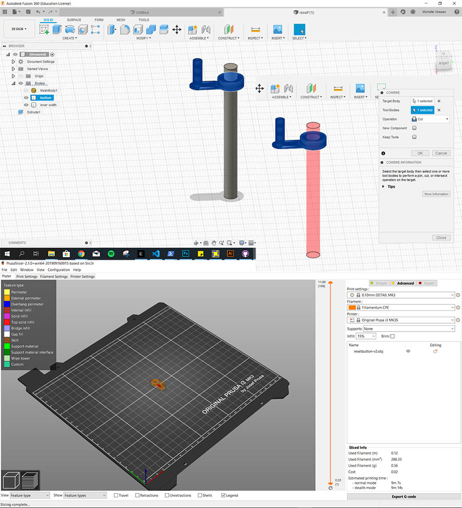
First I made the hole for the screw bigger, because I thought the measurement was incorrect (it turned out I just had to unscrew the screw, I really did not think that through). For this I used Fusion360’s combine function to subtract one body from the other (see image). After slicing and exporting the gcode, I went to print the second button. The weird thing was that although the printer said that the settings for PLA were 215°C for the nozzle and 75°C for the bed, when preheating that would suddenly change to 275°C and 90°C respectively; even when manually lowering this again it went back to 275°C for the nozzle again when I was not looking. This was probably just a case of me not checking the settings in PrusaSlicer.
Final button
The result of the second test was much better so the issue with the first print was definitely the temperature.
Bed leveling
After this I could level the bed (using this tutorial https://www.youtube.com/watch?v=RZRY6kunAvs) with a piece of paper and manually moving the screws keeping the bed in place.
Method:
- preheat the bed to 60 degrees celsius (for PLA) because the bed expands with heat
- counterclockwise: lowers the bed
- clockwise: raises the bed
Apparently I moved the bed too close to the extruder because there seemed to be no space for the filament and the layer printed was very thin. I did two more tests and finally the result was OK - not great but this is one of the reasons why I will work on upgrading all of the axes. For other bed leveling I use the bed leveling procedure on the machine. Since leveling before every print is not a satisfying solution and the result is still unreliable, the whole machine will get an upgrade.
Upgrading axes
The biggest problem with this machine is that it is very shaky, which causes the bed to be unstable and the prints to be of lower resolution when used for a while without levelling the bed. I will work on upgrading the bed to make it more stable. For this I will use these mods:
Tarantula - MGN12 Dual Y Rails https://www.thingiverse.com/thing:2945233
Tarantula - Z MGN9 Rails Mod https://www.thingiverse.com/thing:2947123
Ultimate TEVO TARANTULA upgrade. https://www.thingiverse.com/thing:2761136
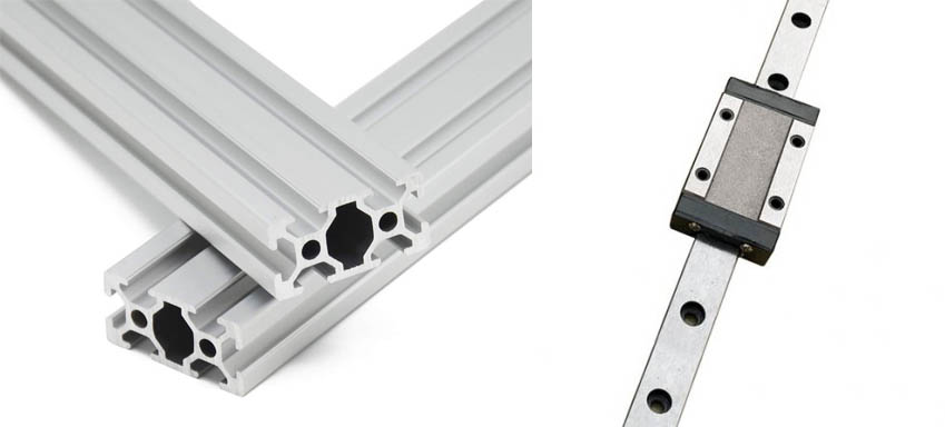
For the Y axis I need the 3d printed parts from the first link as well as 4x 2040 100mm Aluminum Extrusion and 2x 350mm MGN12 Linear Rail with MGH12H block:
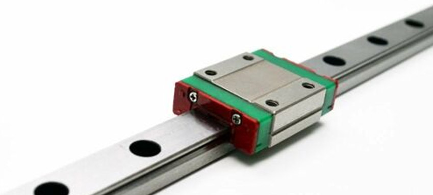
For the Z axis upgrade I need 2x 350mm MGN9 Rail with MGN9H block:
Finally for the X axis I need 1x MGN9 Rails with MGN9H block as well but 300mm long (could be longer but there is no point as the parts on the rails are too wide and 300mm is long enough and cheaper). Some t-nuts with m3 thread are needed to mount all of the rails. For now I have to wait for the rails to be ordered but I can start with 3d printing the parts.
So:
- 2x 350mm MGN9 Rail with MGN9H block
- 4x 100mm 2040 Aluminum Extrusion
- 2x 350mm MGN12 Linear Rail with MGH12H block
- 1x 300mm MGN9 Rails with MGN9H block
Bolts and nuts
Y axis upgrade:
- 8x M3 18mm/20mm bolts to attach the MGN12H blocks to the bed support
- 8-10x M3 14mm bolts and M3 nuts to attach bed carriage to bed
- 32x M5 10mm bolts and M5 T-slot hammer head nuts (size 6) to attach end covers and support guide brackets to extrusions
- 4x M3 8mm bolts and M3 T-slot hammer head nuts (6mm) to attach rails to extrusions
X axis upgrade:
- 4x (at least) M3 8mm bolts and M3 T-slot hammer head nuts (6mm) to attach rails to extrusion
Z axis upgrade:
- 8x (at least) M3 8mm bolts and M3 T-slot hammer head nuts (6mm) to attach rails to extrusion
Recommended print settings
- 0.2 Layer Height
- at least 1.6mm Shell to increase overall strength of your machine
- at least 40% infill
- no raft
Y-axis
Using the Tarantula - MGN12 Dual Y Rails mod, the amount of each part that I printed:
- 4x bracket
- 4x end cover
- 2x support guide bracket
- 2x carriage
- 2x hook-on belt bracket or 1x screw-on belt bracket
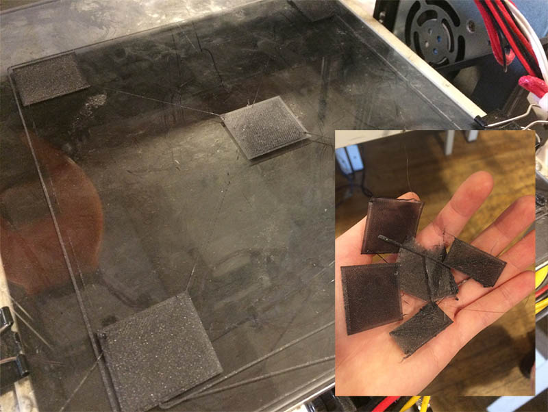
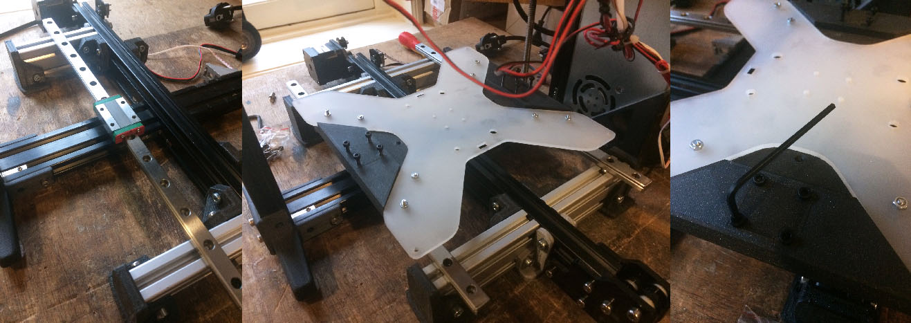
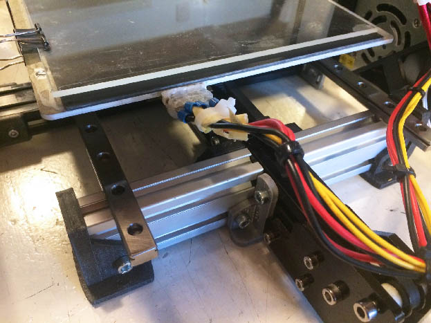
Furthermore, 4x 2040 100mm Aluminum Extrusion and 2x 350mm MGN12 Linear Rail with MGH12H block are needed as mentioned above, and a bunch of M3 and M5 bolts and nuts. I did not use the belt brackets as my acrylic bed has loops for the belt. The hook-on type does not fit, the screw-on would be possible but it wasn’t necessary. See picture of the bed below.
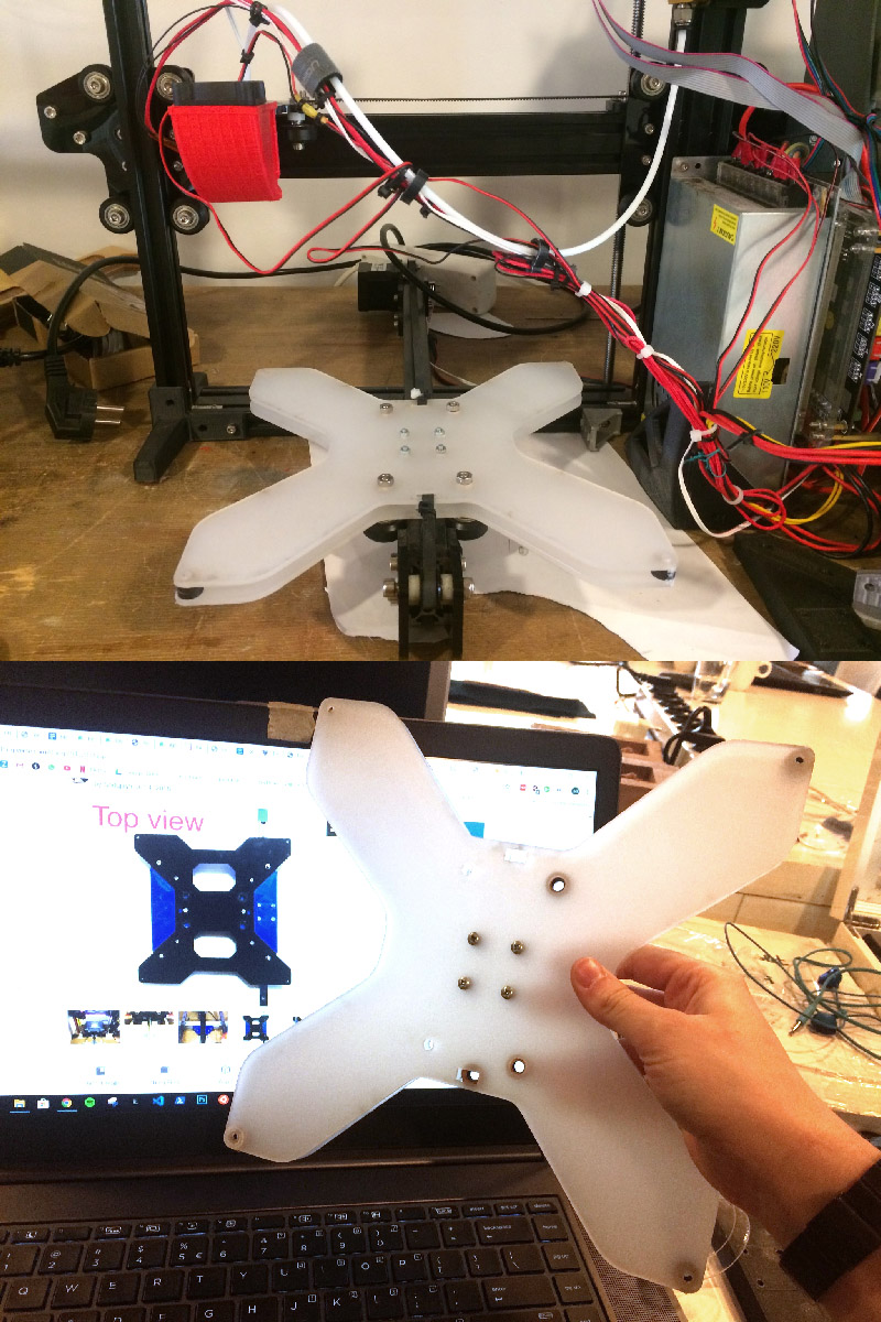
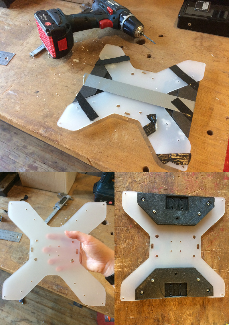
Step 1: attach carriage to bed
Drill holes into the acrylic bed to attach the carriages. My bed has a different shape so I could only drill 4 holes; it also did not fit 100% so I had to be very precise with the alignment. I used M3 bolts (8x; ideally 10x) and nuts.
Step 2: add end covers to 2040 extrusions
Screw M5 bolts with T-slot hammer head nuts into the end covers; leave some space so it’s easier to slide the 2040 extrusion in place.
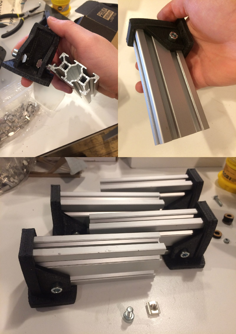
Step 3: prepare and attach brackets and support guide brackets
First I used a drill (5mm) to make the holes slightly bigger as it was a very tight fit. Then what I first did was screwing 2x M5 bolts with T-slot hammer head nuts into one side of each of the brackets. On the other side of each bracket I used T-slot M5 bolts. I did this because I did not want to remove the the motor and belt mount on the 2040 Y-axis extrusion; this way I could leave them there and attach the bracket by twisting the nut on the inside. However, that made it very hard to actually secure it and I also had to attach the support guide brackets so I unscrewed the parts on the front and back of the 2040 extrusion anyway. So: don’t be lazy, use 4x M5 bolts with T-slot hammer head nuts per bracket.
Make sure that the bolts on all brackets aren’t completely tightened yet, so you can easily slide the brackets in from the side of the main extrusion. Don’t tighten them yet.
Step 4: attach 100mm 2040 extrusions, MGN12 rails and carriage
From this step onward I am working on the upgrade with the new Fablab intern Jules. It’s time to align the rails with the 100mm extrusions and attach these to the main extrusion. Slide them into the brackets and tighten the bolts attached to the small extrusions but don’t tighten the bolts attached to the main extrusion yet. Place the rails on top of the 100mm extrusions. Slide the brackets together with the 100mm extrusions along the main axis extrusion until the holes for the bolts on the rails are optimally aligned (but don’t attach the rails yet). Then tighten all of the bolts connecting the 100mm extrusions to the main extrusion. This can be a bit tricky especially if the 3d printed parts are not perfect (which is very likely) so make sure that all of the angles that are supposed to be perpendicular are so. I had to move them around for quite a bit until they were positioned nicely.
Next we attached the rails to the extrusions with 4x 8mm M3 bolts and 4x 6mm M3 T-slot hammer head nuts, using the carriage as a guide by placing it on top of the blocks. Then attach the carriage to the rails using 16mm M3 bolts. We noticed that moving the carriage cost a lot of effort so Jules sprayed it with a good amount of WD-40 oil. It still didn’t move nicely so we also had to reposition the 100mm extrusions so they were perfectly parallel.
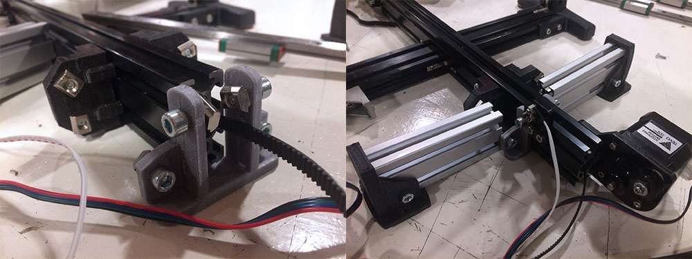
Step 5: attach belt
When the carriage runs smoothly you can attach the belt. Make sure it’s as tight as possible. We reattached it about 5 times as we tried different ways to tension the belt between both ends. Before the upgrade, the belt went through the center of the extrusion, but this created an angle between the belt and extrusion that caused extra resistance and wear. The belt also didn’t touch all four pulleys: it hovered a bit over two of them. This isn’t a very big problem, as long as the belt has a proper grip on the pulley on the stepper motor. The best solution we found was to run the belt over the top of the extrusion and not use one of the pulleys at the back, the side where the stepper motor is not located.
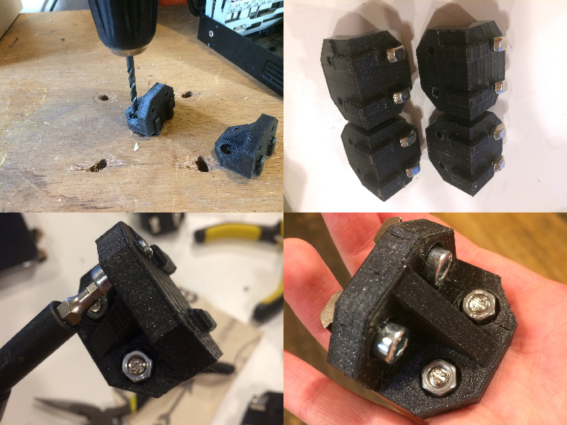
Step 6: position bed and final touches
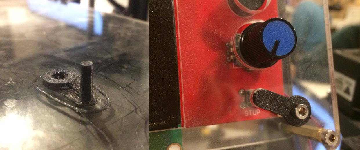
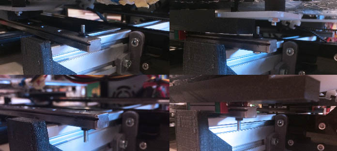
After that we placed the bed without securing it yet to do a first test with the machine on. At this point we realized that we needed something to indicate the maximum ends of the rails, because otherwise the carriage would run off the rails. We had to take into account the height of the carriage, which is only a few millimeters above the rails. Eventually Jules came up with the simple but effective solution of a screw in the holes at the ends of the rails, with a small spacer in between, so that the screw protrudes about a millimeter above the rails.
In the meantime, Jules re-soldered and insulated the power supply of the bed with hot glue.
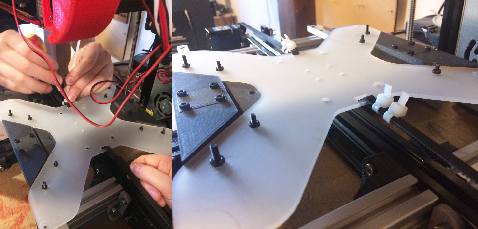
We then placed the bed with 4x 20 mm M3 screws with 3 lasercut spacers (3 mm each in total 9 mm each) between the acrylic sheet and the bed, which were first between the two acrylic sheets. Before this, there were long screws in the bed and the acrylic plates with wheels attached to it to level the bed manually, but this was very inaccurate and inconvenient. Now one of the acrylic sheets is gone and it is no longer possible to level the machine manually, but for this we will add a bed leveling sensor to the print head. If everything turns out well, it won’t be necessary to adjust leveling manually after the initial leveling, as the machine is no longer as sensitive to shocks as before.
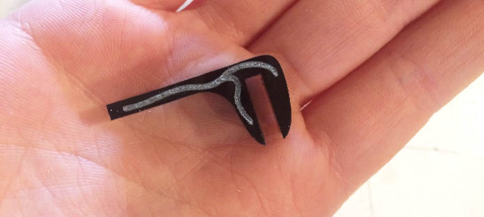
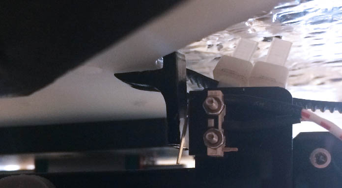
We also found out during the Y homing procedure that we no longer had a point of contact for the endstop, since the wheels that were previously attached to the carriage have now been replaced with the rails and blocks. For this I designed a small clasp in Illustrator (with a lovely organic Y-shape for the y-axis) to lasercut. Unfortunately it was too long, so I had to cut off a piece of about a centimeter. The clasp fits precisely on the acrylic bed and is easily positioned relative to the endstop.
After this we tried the homing procedure again. The carriage moved slowly and we received an error from the printer because the stepper motor wasn’t able to move the bed. Then we found out that the belt was suddenly very loose; presumably it was stuck somewhere at an earlier moment. We solved this by placing the back pulley holder a little backwards so that there was more tension on the belt. A more optimal solution would be to have a butterfly screw that you can turn to tighten the belt, since you now have to move the entire pulley holder to adjust the tension.After re-tensioning the belt, the machine ran beautifully so that concludes de Y-axis upgrade.
X-axis and print head upgrade
Using the Tarantula - Z MGN9 Rails mod, the amount of each part needed according to the description:
- 1x X rails belt tensioner 1/2
- 1x X rails belt tensioner 2/2
- 1x X rails belt tensioner knob slide spacers
- 1x X rails motor mount
- 1x Z rails left motor mount
- 1x Z rails right motor mount
- 1x extended lead screw gantry
However some of the parts in the Tevo can be reused: we already have a right motor mount for the Z-axis, so I don’t have to print that. I replaced the left motor mount with this part, as it is the mirrored and edited version of the one we have for the right motor. This way the Z-axis is symmetrical. Other than that we printed all of the X-axis parts and the lead screw gantry for the second motor.
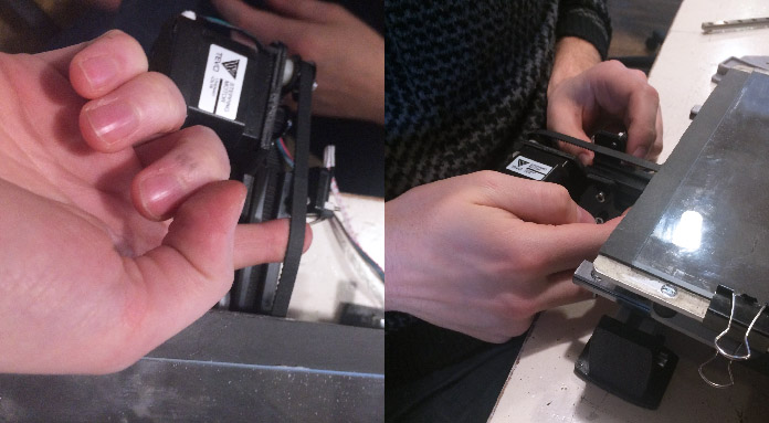
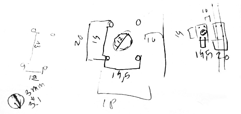
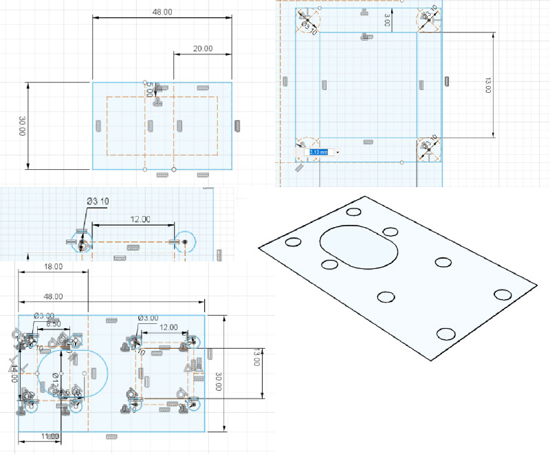
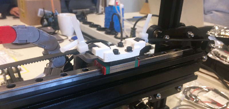
We removed the print head and attached the 300mm MGN9 Rails with MGN9H block to the X-axis extrusion with some 8mm M3 bolts and 6mm M3 T-slot hammer head nuts (three each). We determined that it would be wise to upgrade the print head using parts we designed ourselves. The print head we had before was very bulky and wide, and the acrylic base was very easy to bend so it wasn’t very stable. I designed a small board to connect the hot end to the MGN9 block, that I lasercut out of the acrylic base that we had before, so we didn’t have to use any new acrylic.
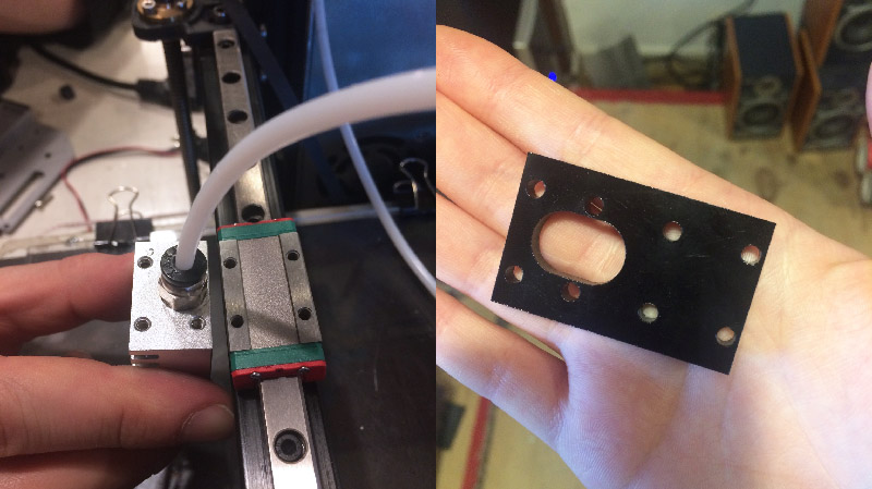
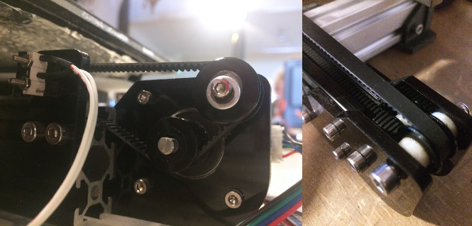
To connect the belt to this construction, we used the Y-axis screw-on belt bracket that I had printed before but not used. To be able to screw it onto the MGN9 block, I used a milling bit on a hand drill to enlarge the holes, and used 16mm M3 bolts and some washers to screw them in. A demonstration of how smooth it runs below.
Tensioning the belt was pretty simple, we didn’t change the positioning of that (for now).
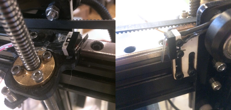
At first the endstop of the X-axis was attached to the print head but since our print head is very minimal now, we moved this to the side. To attach it Jules first hot glued it to test the position, and then lasercut a little endstop holder.
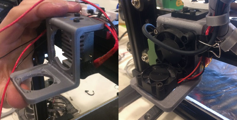
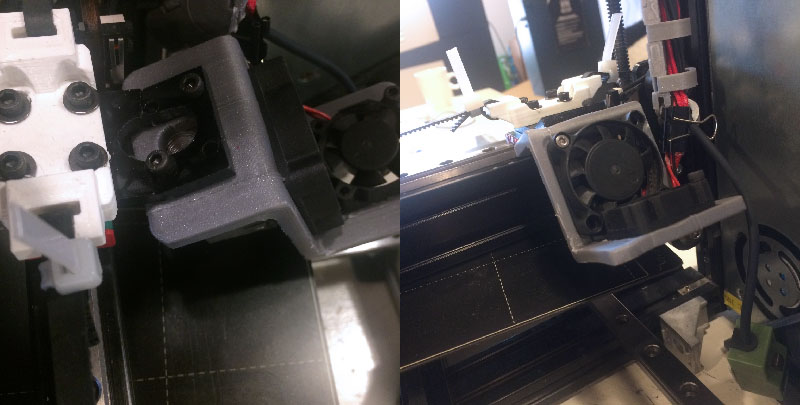
Jules worked on the design of the print head: the ‘everything holder’, including fan duct and a grip for the new bed leveling sensor. Below the first version:
While testing the bed leveling sensor on a first prototype of the print head we found out that the sensor actually detects metal while we have a glass plate to print on. We then tested with aluminium tape on the glass plate which worked, but that would not be a good solution since the standard bed leveling procedure is in nine different places and we cannot put pieces of tape on the surface, because then the bed will no longer be nice and smooth. We then tried it with aluminium foil under the glass bed which it could detect, but the distance between the bed leveling sensor and the glass bed is too small for the nozzle to stay above the plate.
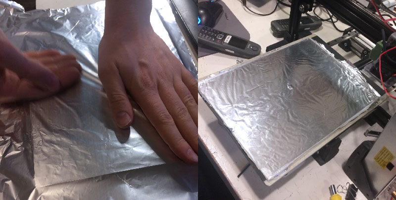
The best would be to replace the glass bed with an aluminium bed but for now we will try to fool the machine by putting an aluminium bed from another machine for the bed leveling and then printing with a negative offset of the thickness of the aluminium bed. However, while trying to fool the machine the sensor suddenly didn’t notice the plate and tried to go right through, breaking the print head in the process. The 3d printed part had to be modified anyway and the acrylic connector only takes 2 minutes to lasercut so it’s not a big problem.
Continuing where I left off after a few months
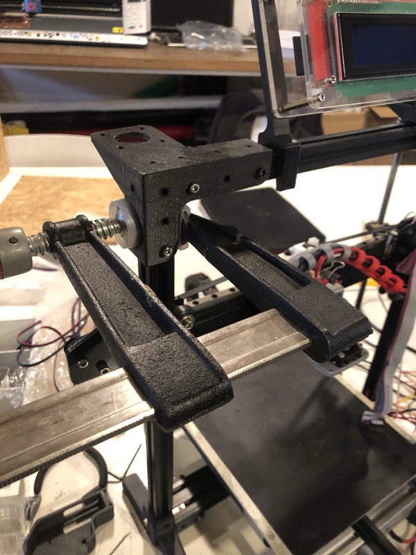
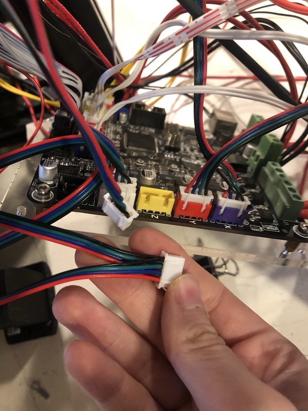
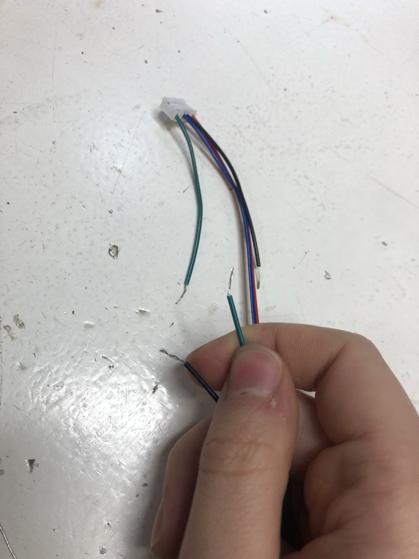
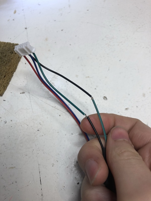
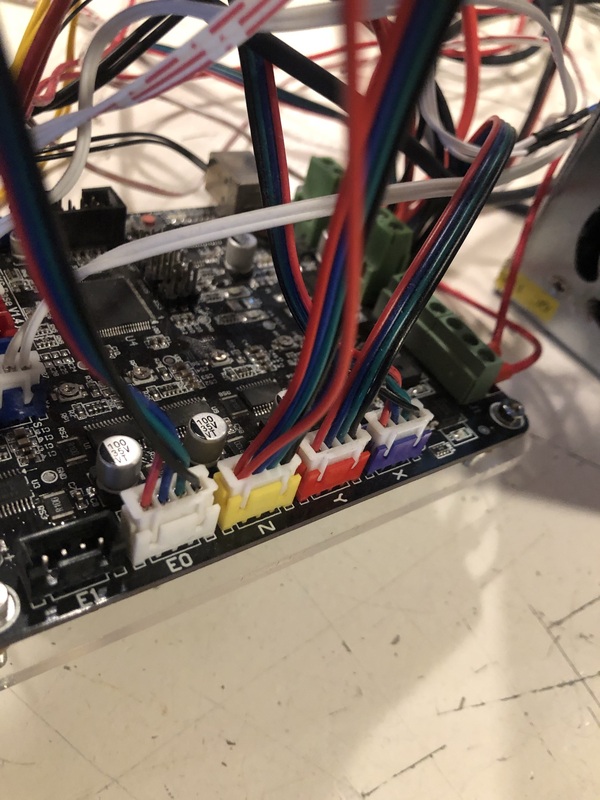
So a whole pandemic happened (and is still happening) and I couldn’t finish my internship properly… In november 2020 I was able to return for a few times, but it had been a while since I worked on the machine with Jules so it took me a while before I figured out where we left off. I started with adding the second motor for the Z axis upgrade. I replaced the piece connecting the left Z axis and top X axis extrusions and installed the left motor mount. I had to use a clamp to get the 3d printed part to fit. Since there’s now two motors instead of one for the Z axis but only one input for the connector, I had to use a different cable consisting of two cables going to one connector.
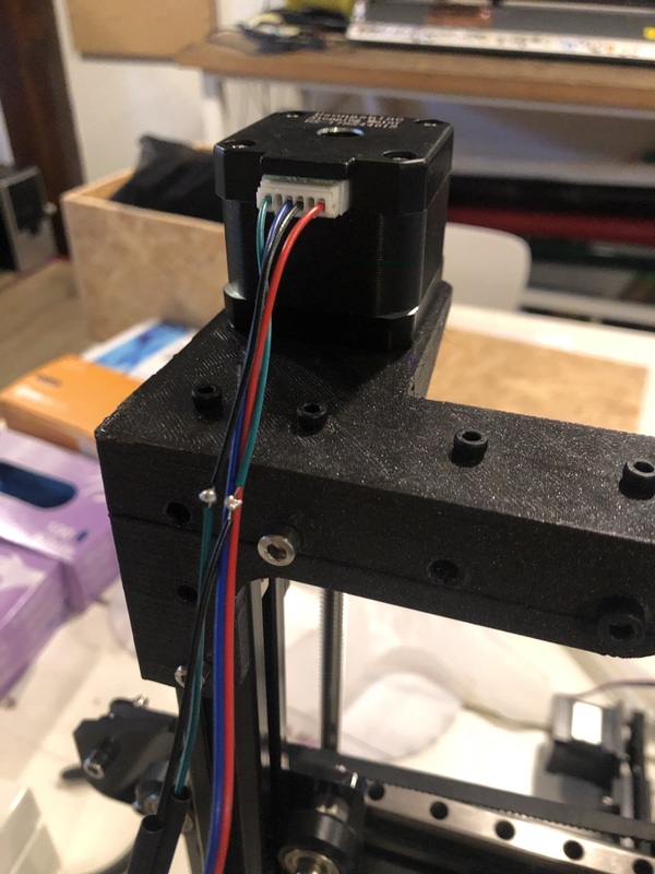
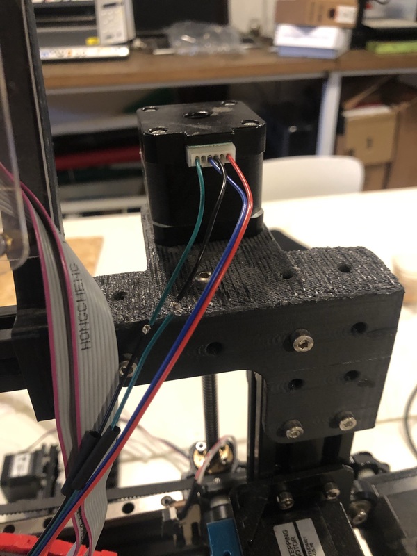
After trying them out carefully (taking .1mm and 1mm steps) I realized they were moving in opposite directions so I had to flip and resolder 2 wires on both motors cables.
Compiling with PlatformIO
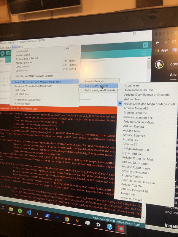
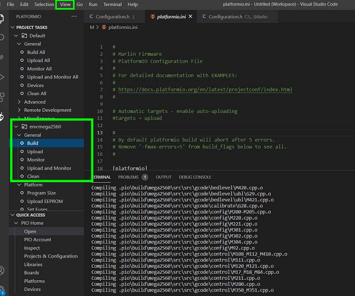
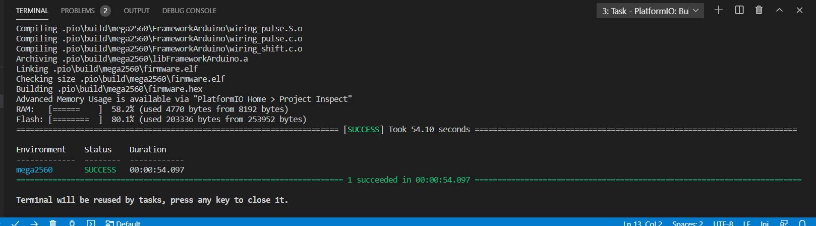
I didn’t know exactly what changes Jules had made to the Marlin software to make the endstop move to the right instead of the left (which is standard). It’s also impossible to reverse the connection with the board on the Tevo to retrieve the configuration since it’s the compiled version on there anyway. So I decided to start over with the standard Marlin EasyConfig for the Tevo Tarantula by Jim Brown and work from there so I could learn how it works and why it does what it does. I am using PlatformIO in Visual Studio Code to compile the code, since working in Arduino kept resulting in errors while compiling (fork/exec C:\User\Documents\ArduinoData\packages\arduino\tools\avr-gcc\7.3.0-atmel3.6.1-arduino5/bin/avr-gcc.exe: The filename or extension is too long.) and after troubleshooting for a few hours I figured I would try PlatformIO instead. PlatformIO didn’t have any issues whatsoever and I can just compile directly from VSC so it’s wonderful. The board is MKS Base V1.4 (select arduino MEGA 2560).
Z axis homing with the SN04 bed leveling sensor
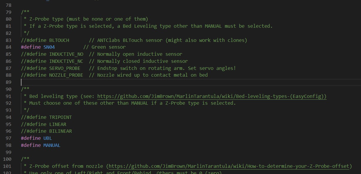
Being able to compile the program and to send it to the machine, I could finally get started with tweaking. I defined the Z probe sensor that we installed in march. This is the SN04 sensor. At first Z axis homing was just returning to the zero point, after a M48 probe accuracy test (putting an aluminium bed/piece of aluminium foil as reference on the glass bed; glass bed will have to be replaced) Z axis homing works; 0 is now a few mm’s above the bed which can be fixed in the configuration.
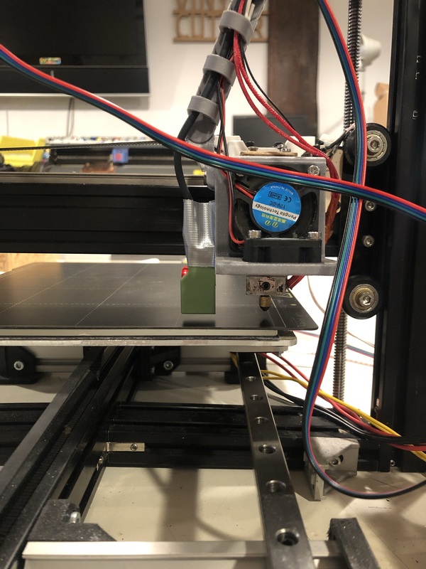
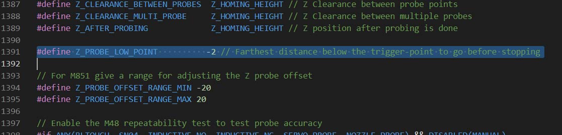
I need to measure how high the SN04 is placed above the bed, so I can define how low the nozzle can go. Right now, after leveling the nozzle floats above the bed when Z is 0.
Y axis homing
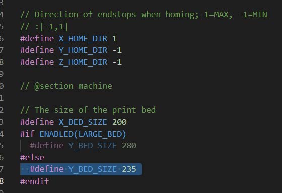
Y axis homing works fine, moves to the back and then I can move it +200mm; I changed this to +235mm since that was how far I could move the bed.
X axis homing
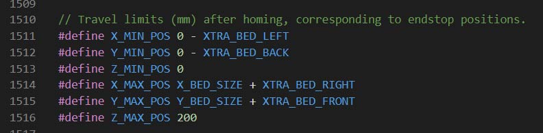
X axis homings has some issues, the machine moves to the right after changing the end stop from MIN to MAX, but then the right is 0 and it thinks it cannot move to the left (minus) so I have to let the printer know that the right X axis end stop is not 0 but +200mm (or move the endstop to the right or to the print head again). I changed the bed size so it could move the X axis to minus -160mm but then later I tried changing X_MAX_ENDSTOP_INVERTING to false but then it would only move to the left again (which makes sense since it was going in the right direction anyway). After not being able to find out how to make the machine understand that X max endstop homing means that that position is the outer boundary and not 0, I decided to move the endstop to the left of the machine (where it usually is located anyway). So still not connected to the print head which was why Jules decided to move it.
Z axis homing
https://github.com/JimBrown/MarlinTarantula/wiki/How-to-determine-your-Z-Probe-offset-(EasyConfig)
Case
https://www.thingiverse.com/thing:3456767
Future plans
- A flippable construction for the z probe sensor so non planar slicing would be possible
- Upgrade Y axis with MGN rails