CNC Milling Machine (3D tutorial)
I wanted to create a reusable glove mold using the 3D milling abilities of the Shopbot. This is also one of the Fabricademy assignments, textiles as scaffold.
Step 1: modeling in Blender MakeHuman and Fusion360
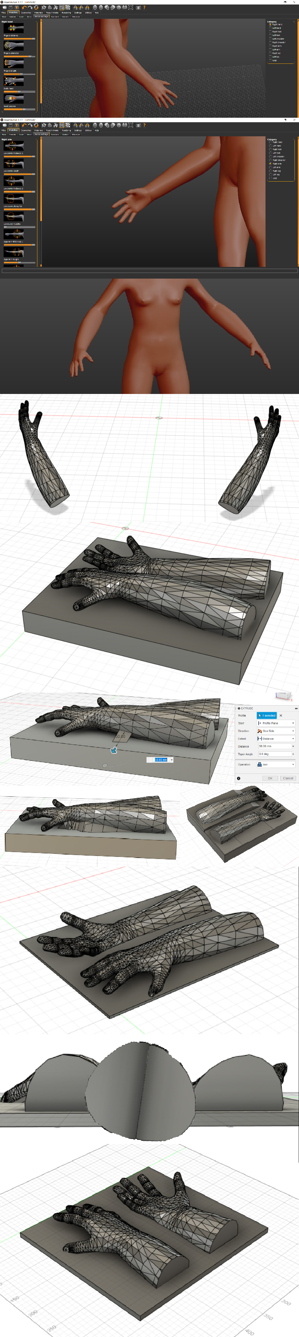
I started with MakeHuman, so I could easily design a hand and an arm. I didn’t want to make a mold of my hand as I have very small hands and I wanted my gloves to be a bit more uniform. I then saved my model as an obj and imported it in Fusion360. I removed the rest of the body using the combine tool (cut function). I started with the right glove, the left one I will do at a later point (so I can use a different technique or improve the design). I forgot to take the maximum length of the milling bit into account so I tried different ways of making the lowest point higher. In the end however I found a milling bit that was quite long that I could use so I ended up changing my model again. I also made it shorter to save time and material and I felt that the glove would not improve from making it that long. After rotating and repositioning the model for way too long I was pretty content but next time I should make sure my design is more fit for what I want to use it for. I will make a 3d scan of my own hand and scale it uniformly, or I will figure out how to change the pose of the hand with Blender. It was cumbersome to position the glove in such a way that both sides of the mold are useable because of the bent fingers.
Step 2: creating toolpaths in Partworks 3D
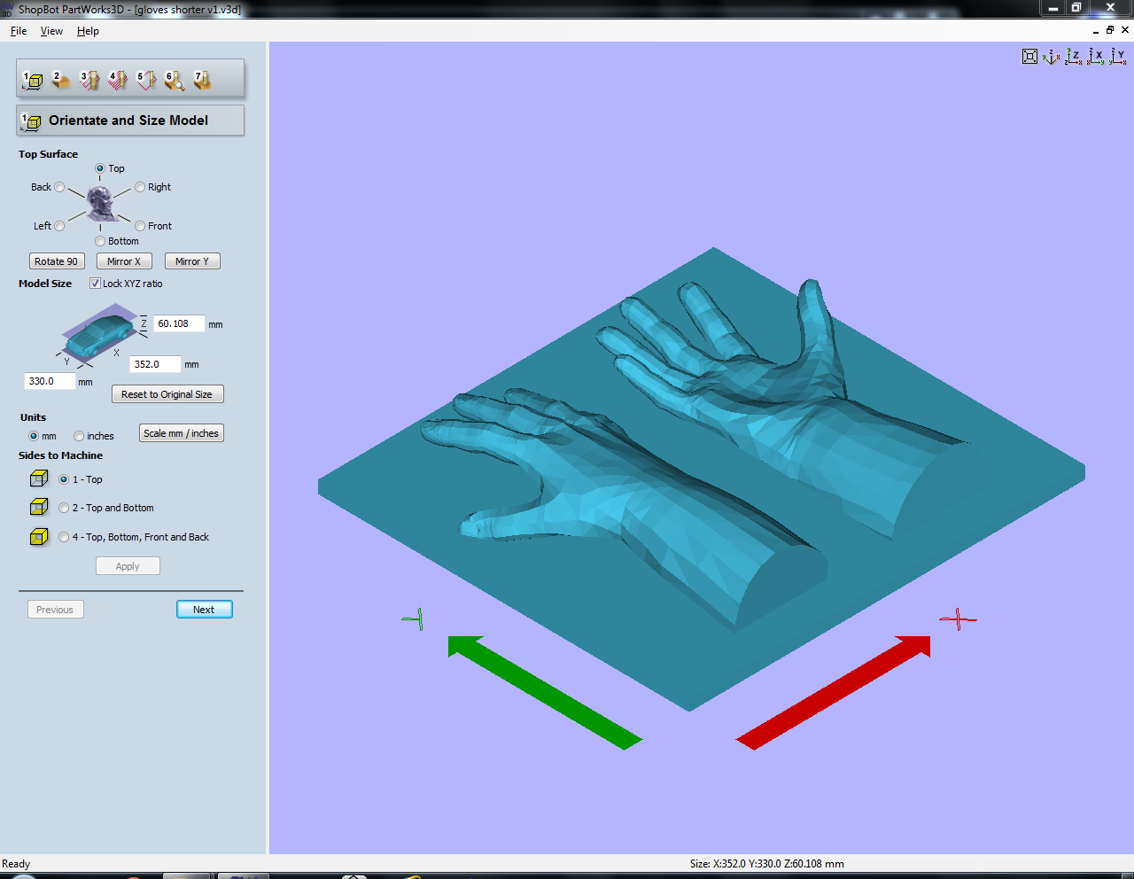
For 3D milling we use Partworks 3D. It’s also possible to use VCarve Pro but Partworks 3D is more user friendly. Start with importing the 3D model (stl/obj).
-
Specify orientation and size of the model. You can change the top surface of the model. I picked the top since I designed my mold keeping the machine’s orientation in mind. The model can be scaled here if you haven’t done so already, always check if the size corresponds to your design! Select Top for sides to machine and press Apply.
-
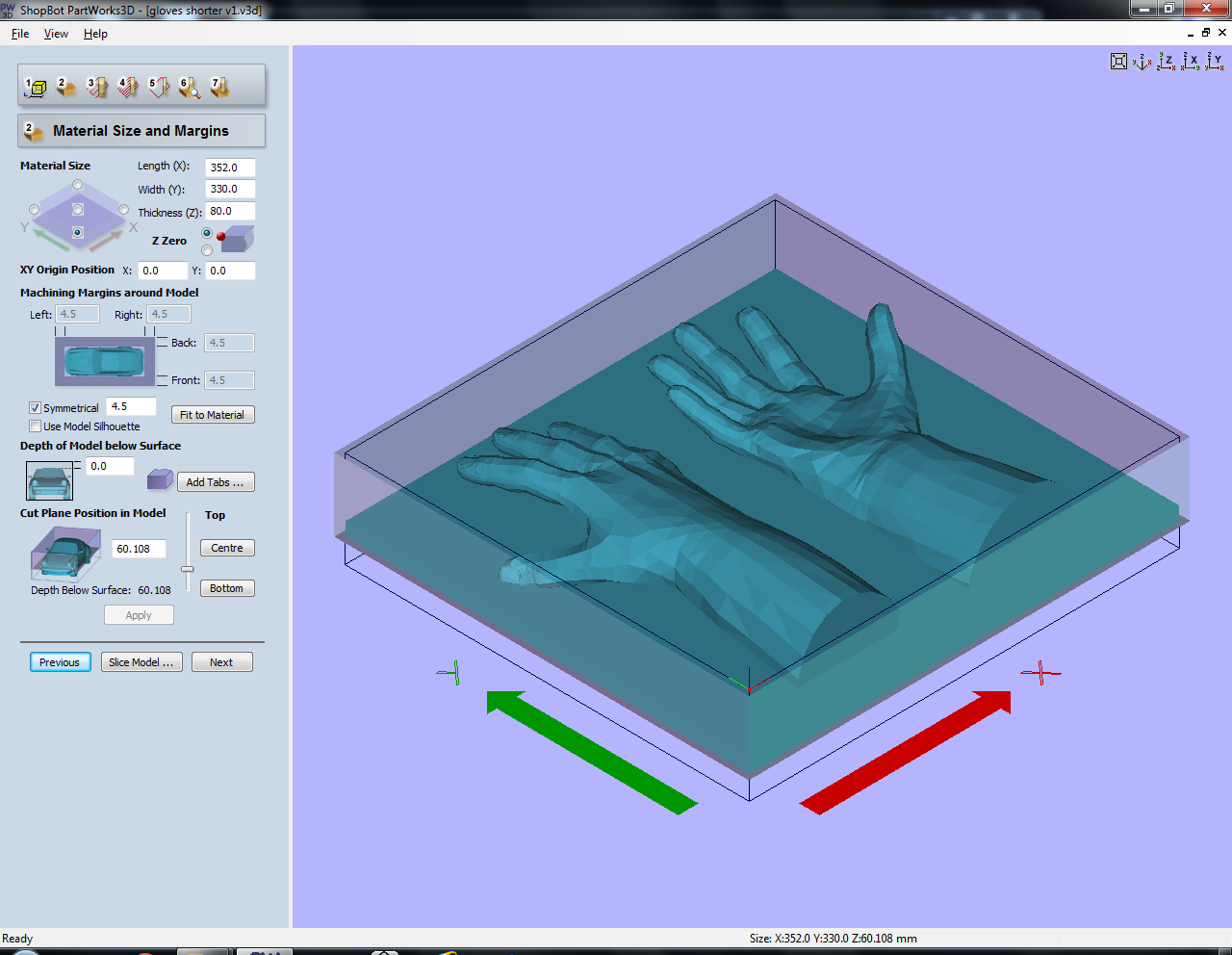
Set material size and margins. You can actually fool the machine by setting the material size to the model size. If your material is thicker than your model you also don’t have to specify this, as long as you zero at the top of the material. Don’t forget to set X and Y to the left bottom corner of the material as I forgot to change this and the machine started milling somewhere else as I zeroed the machine in the left bottom corner. You can of course leave X and Y in the center but you have to zero the machine accordingly, and it is in most cases most accurate when you use one of the corners of the material. If necessary you can add margins. For my model it wasn’t necessary as I already added them by giving my model a base plate, but I accidentally added them anyway which made milling take longer. The cut plane position in model specifies the depth below the surface of the material. unless your material is very irregular on the top surface I would leave this as high as possible, so milling will go faster. Press apply when finished.
-
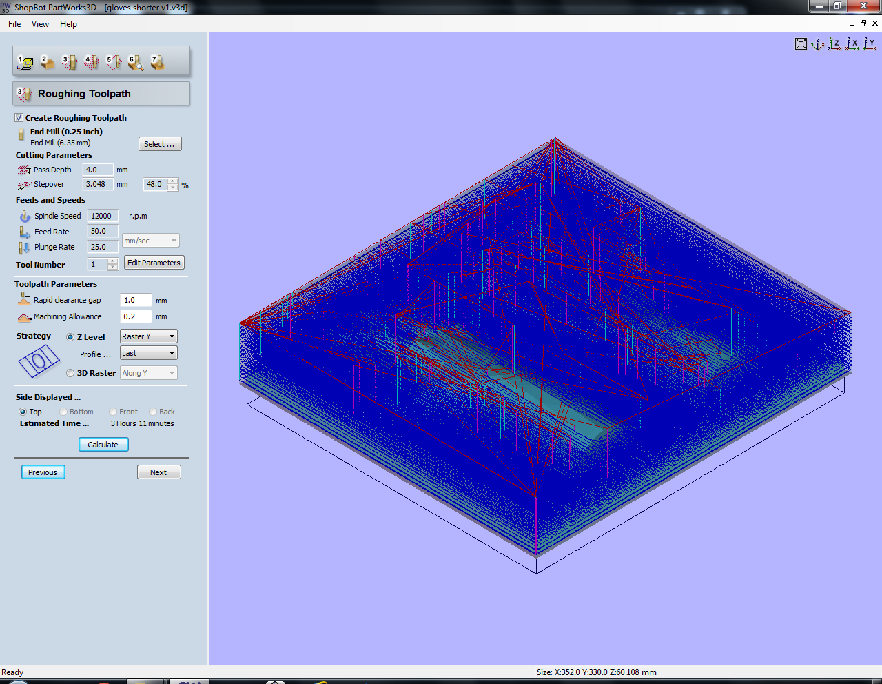
Set the roughing toolpath: this is the first run of the machine, where it mills away material layer by layer, top to bottom. Select the milling bit you want to use. I used a quarter inch four flute end mill, because this was the only long end mill I could find. I wanted to use a 5mm one but they were all too short so I would not be able to cut through all of the layers (about 5cm deep). I used a spindle speed of 18000 RPM (not 12000 as specified in the screenshot), a stepover of 48%, pass depth of 4mm and plunge rate of 25mm per second. Because I am using a four flute, the feed rate has to be lower than usual (120mm per second is usually fine for foam with a two flute) since it takes more time for a four flute to get rid of the material. I increased the feed rate from 50 to 80 while I was milling since it didn’t seem to have any issues with milling the foam. Machine allowance is how much material is left to sand away. Using an Y-raster strategy is easier for the machine as the bridge doesn’t have to move constantly. Press calculate to get an estimate of milling time.
-
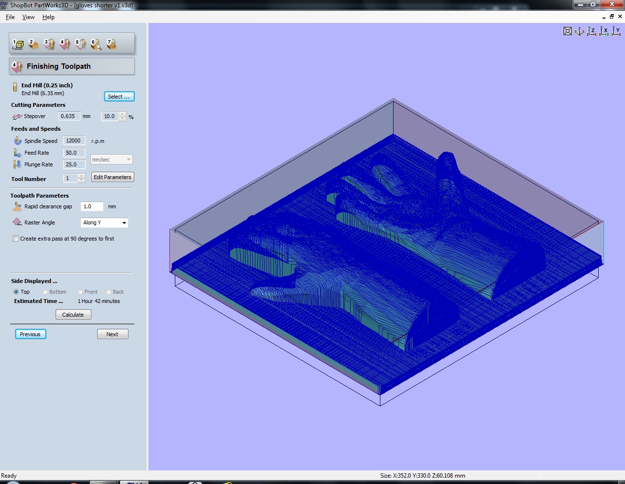
The finishing toolpath is the second run of the machine where it mills away material going up and down (non-planar). You can change the mill if you want but I used the same one as before. Using a raster angle along the Y axis is again easier for the machine (and slightly faster) so that’s what I did. The stepover is much smaller here, the smaller the higher the resolution. I used a spindle speed of 18000 RPM (again, not 12000 as specified in the screenshot), a stepover of 10% and plunge rate of 25mm per second. Then press calculate.
-
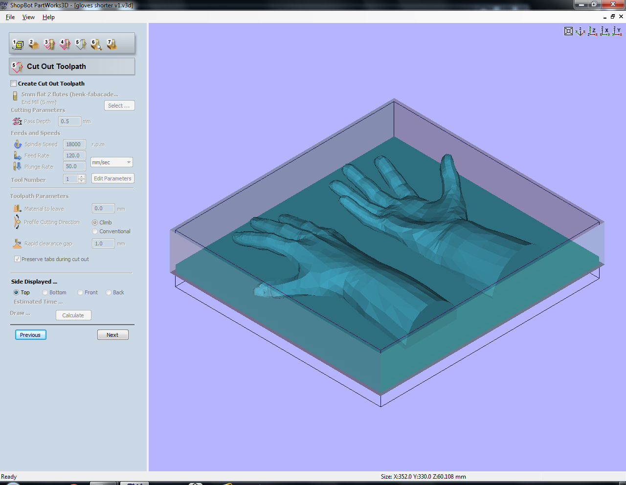
A cut-out toolpath can be specified in this step but when using foam it’s much faster to do this by hand. If you need a perfect cut-out however this is the place to be.
-
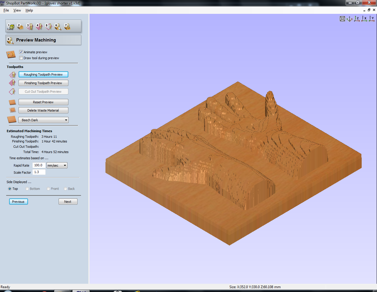
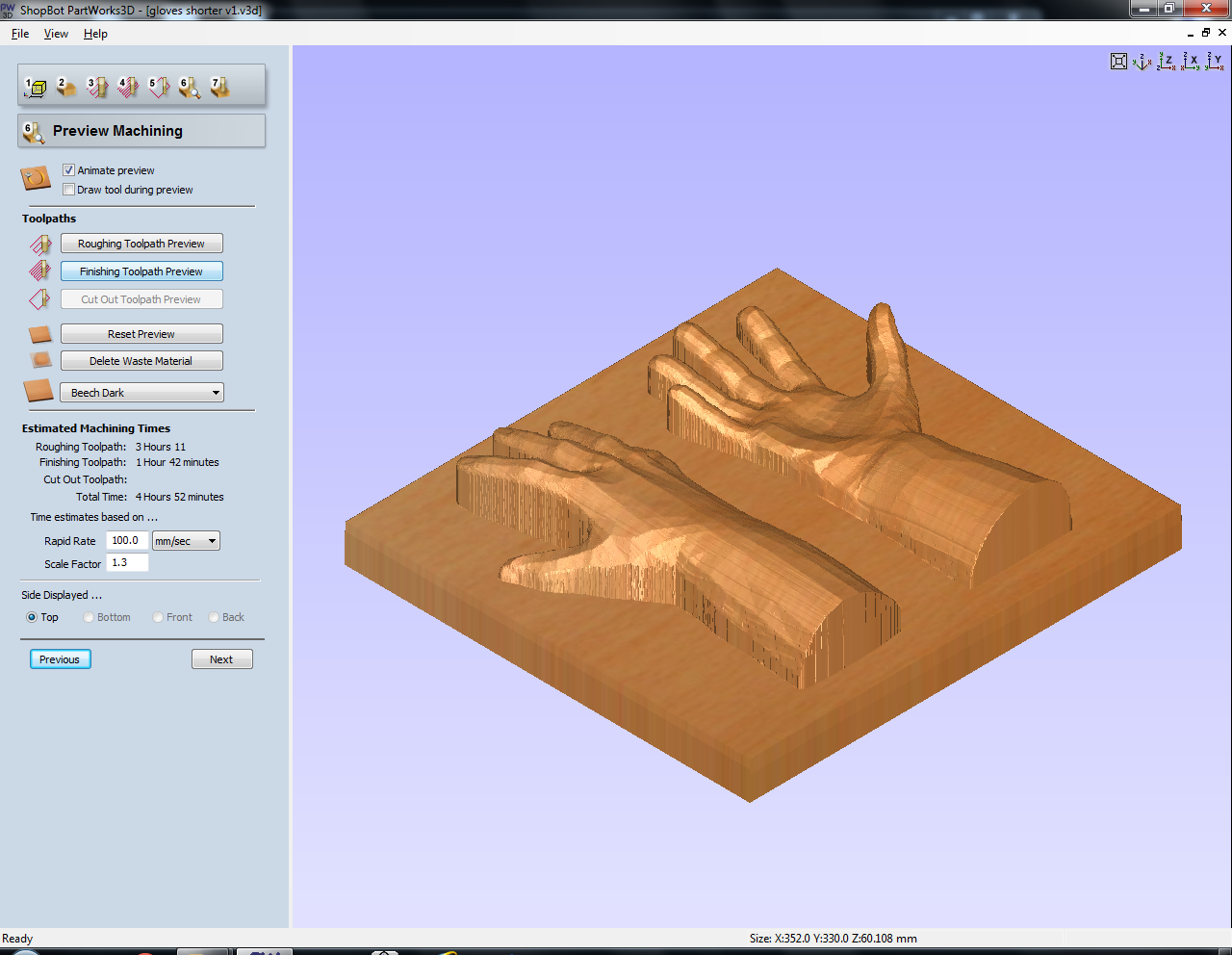
In this step you can preview your toolpaths. Since the machine cannot mill under the fingers, straight lines are created downwards. It’s not a problem for me, but you should keep this in mind while designing. You also have to take the diameter of the mill into account; some of the spaces between the fingers were too narrow to mill all the way through.
-
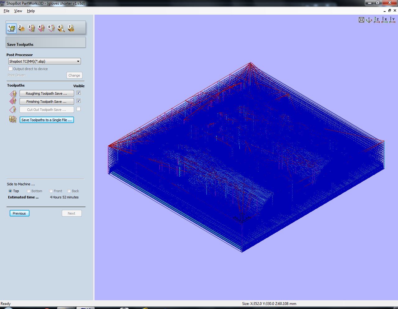
Save the toolpaths to a single file if you don’t have to change the mill in between and want to do the whole design in one go.
Step 3: milling the model out of foam
For the setup of the Shopbot, check out my documentation on the CNC milling machine)
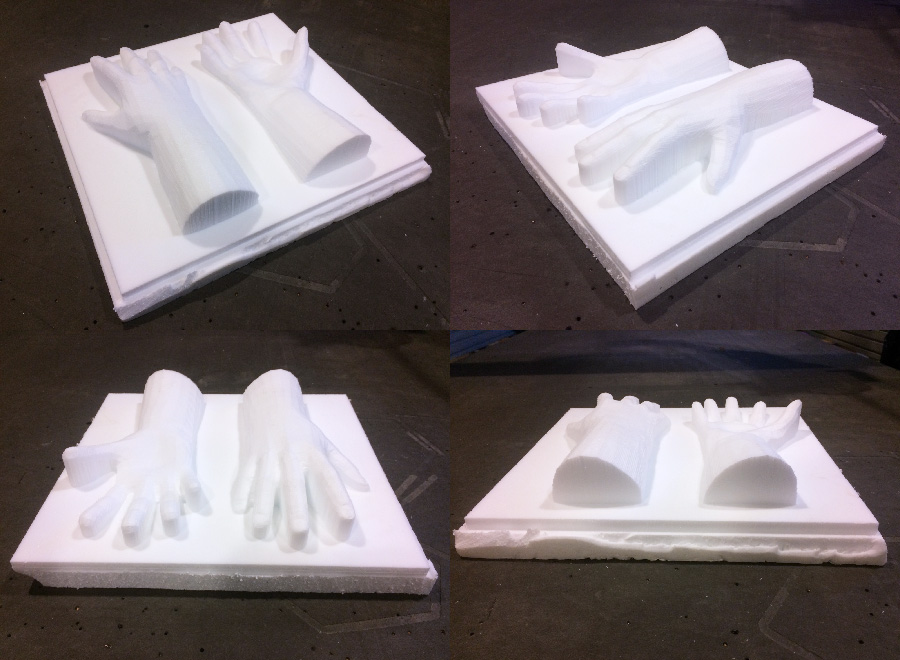
It took about 4,5 hours to mill. Process of milling:
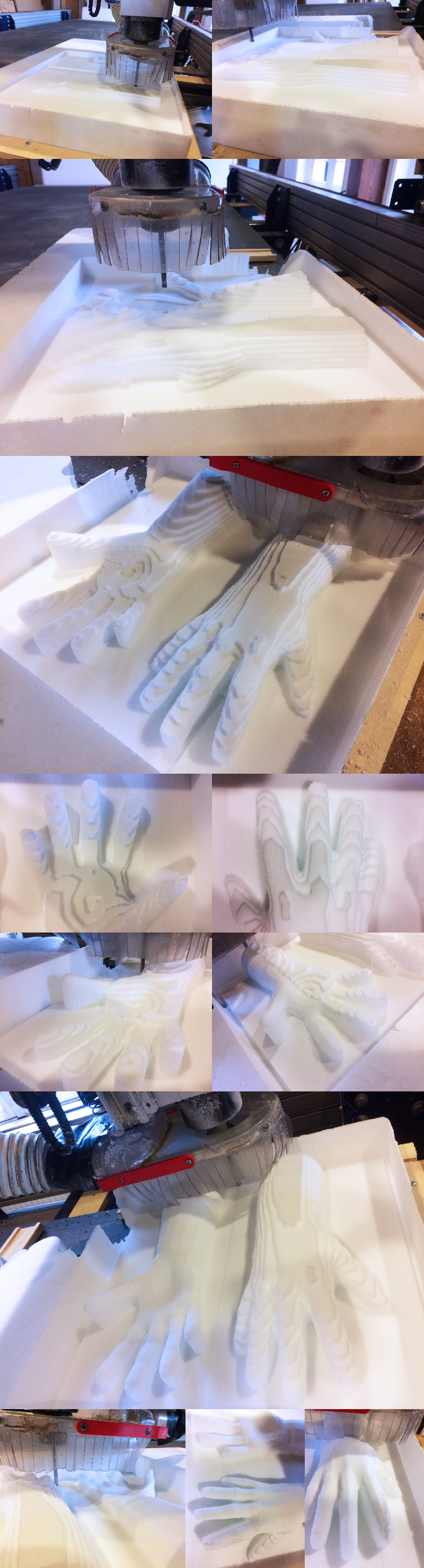
Final result: