Milling PCBs with the Roland Modela
Linked to the Fabacademy electronics production lecture.
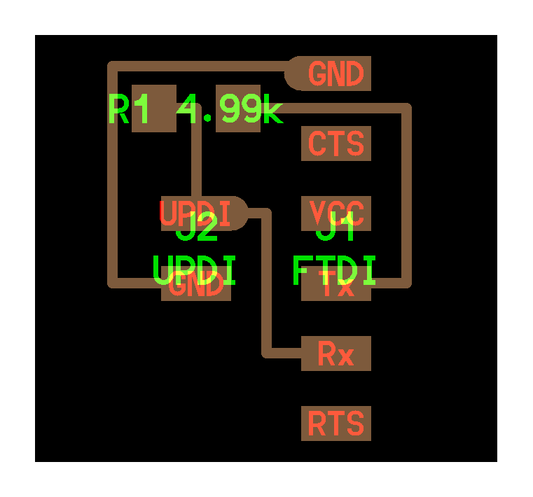
Serial communication
To communicate with the program you’ve made you need the ftdi (Future Technology Devices International Limited, you can buy a usb cable with one integrated and it’s like 20 euros) it’s serial communicating over usb with the board. it uses 2 (of 6) pins for the communication (1 sending, 1 receiving)
- rx: receive
- tx: transmit
- UPDI: rx and tx on one pin (ftdi with a bridge, advantage is one less pin)
Brands of microprocessors
- ATtiny/tinyAVR (8 bit)
- SAMD (newer, cool features, up to 32 bit processing, you program them with the J tech, not with a updi)
- ATmega/megaAVR (more pins, more memory, more possibilities)
Programming interfaces
UPDI (Unified Program and Debug Interface, programming and debugging, newer and more options), ISP (in-system programming, no debugging, for older chips) and JTAG (Joint Test Action Group; debugging interface) are all protocols for programming a micro controller, determined by the chip you’re using.
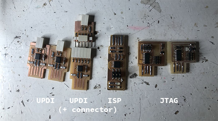
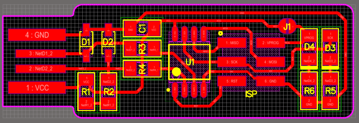
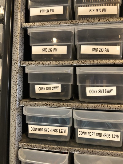
The boards in the picture above can be found here.
Below the boards for the UPDI and the FTDI connector + UPDI.
The ISP is the ‘Brian board’.
JTAG boards:
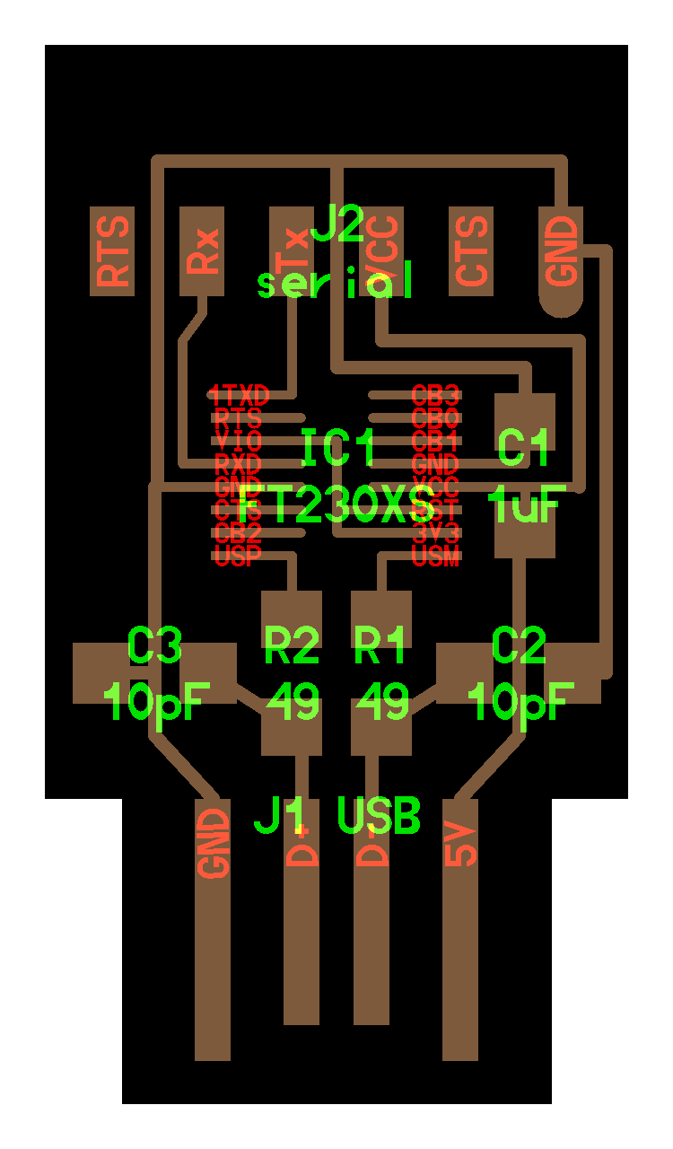
- usb > ftdi (not for programming a micro controller but for interfacing) > serial
- assignment is to make a PCB: learning how to produce electronics by milling boards and soldering components (going to start with a UPDI now)
You gotta program them to use them to program others!!!! Otherwise it’s ‘dead material’, it needs instructions. So this is why we’re starting with a programmer PCB. You can’t program with the ftdi but you can use a ftdi cable (later).
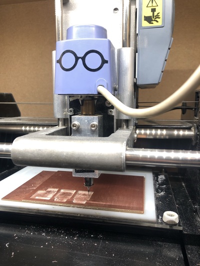
Roland Modela
- .006mm precision (in theory)
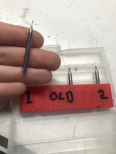
- Milling bit depending on what you use (.4mm for traces, .8mm to cut it out)
- Used the machine to make a perfectly leveled bed (milling a perfectly flat bed, a pocket) out of acrylic melted to the acrylic machine bed
- Copper plate is the sacrificial layer; has to be replaced from time to time
- The copper plate (fr1) has pressed paper in between
- We don’t mill fr4 (with glass in between) because it ruins your machine (dulls the bit very quickly) and it’s dangerous to have glass dust (to breathe it in or get it in your eyes)
- Stick the board to the bed with double sided tape (clean surfaces first with sticker remover); completely fill it up but don’t let them overlap! otherwise it’s not level
- Press the board tightly and perfectly flat with some clean fabric on the bottom and the acrylic on the top
- Tighten it snugly, not aggressively
- Don’t screw the mill in too tightly or you have to replace that screw a lot sooner
- If you move the origin, you also have to redo the Z axis alignment. This has to do with the imperfections of the board; it does remember where the 0 point was but just to have it as precise as possible you have to redo it
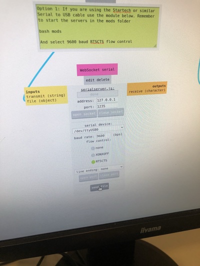
- After starting mods, go to the program (Milling with the MDX), close WebSocket pyserial, close the pyserial port, then close socket and port for the WebSocket serial, then open socket and open port there. Try moving to the origin to check if there’s a connection.
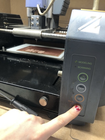
- Turn it on > machine automatically goes to machine home, it’s in view mode (can turn that off with the view mode button)
-
Now replace the milling bit if it’s not the correct one. You can’t release it and let it fall out because it will break; put one finger against the milling bit and take it out in a controlled way
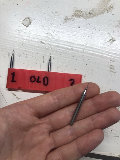
- The .4mm milling bit we are using is a two flute. Put them in the correct place in the box!
- Put the milling bit up all the way in
-
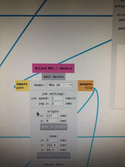
Start mods (type mods in the terminal) to fire up a serial server connected to the Modela. Select MDX Mill > PCB
- Close the pyserial socket (right), open the other serial.js websocket (left)
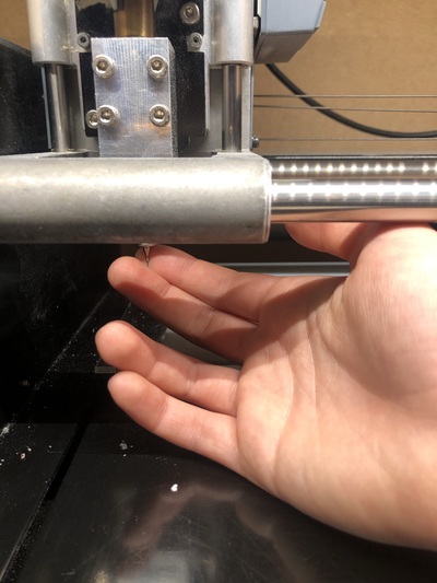
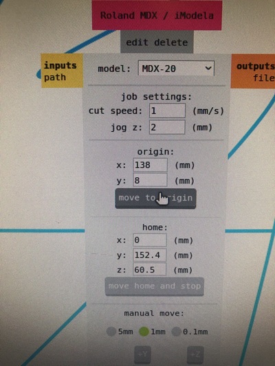
- Go all the way down with the machine (the buttons on the machine, not in mods) and then a little bit higher (can only do this when the milling bit is all the way up). The bit is floating above the material. Now we can lower the bit with support of two fingers to touch the material (the actual material, not the sacrificial layer); wiggle it in case there’s dust so it’s perfectly lying on the material) and then secure it. Always write down the origin! Or take a picture of it. The machine is now ready. Set the origin in mods, so keep changing the values for x and y there until you are where you want to start; don’t use manual move for this.
-
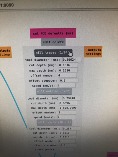
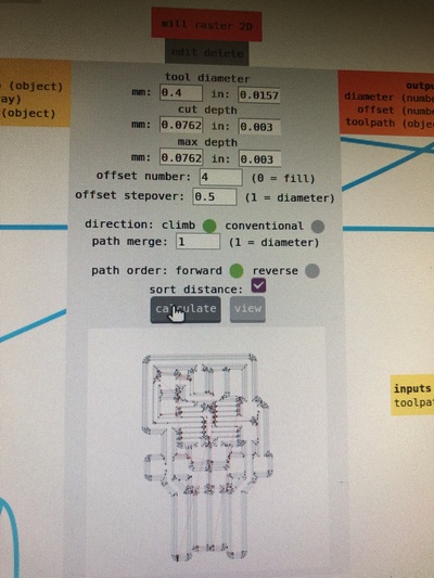
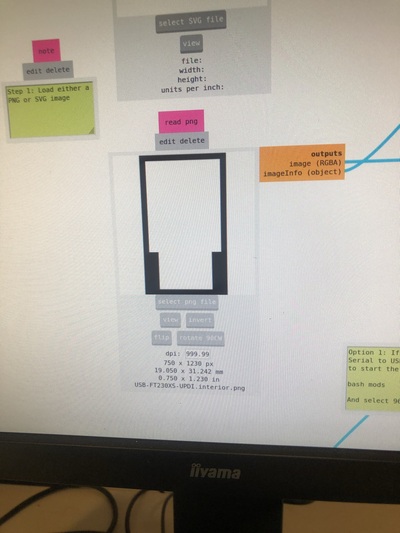
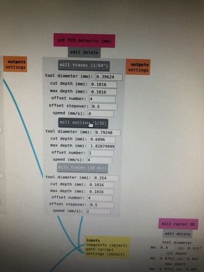
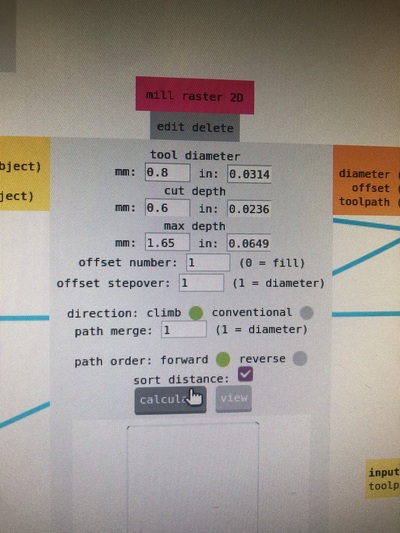
Now you start with the traces in mods (PNG or SVG); one image at the time. White is the area you want to keep. Don’t forget to put DPI as 1000. Put PCB defaults in mm. Cut depth and max depth is 0.003 INCH (numbers from experience); this will cut through the top copper layer. UPDATE 15/02/22: NOW IT’S O.OO2 INCH FOR CUT DEPTH AND MAX DEPTH AND THE SPEED IS 4MM/S FOR A 1 FLUTE 0.4MM MILL.
-
Offset number is the (maximum) amount of traces from the lines you want to keep. 4 is nice, easier to solder etc. 0 takes off everything except for the lines.
- Offset stepover is half of the tool diameter so you are sure it takes off everything.
- Forget about climb and conventional milling for now. It has to be climb.
- Path merge is 1 (diameter of the tool). Path order forward/reverse. Just use forward. If your traces are too close it sort of overlaps itself.
- CALCULATE
- Cut speed 1mm/s for this milling bit (UPDATE: now 4mm/s)
- Web socket > send file and it will start milling straight away
-
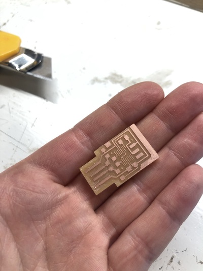
Vacuum the dust
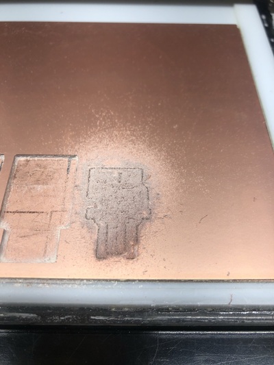
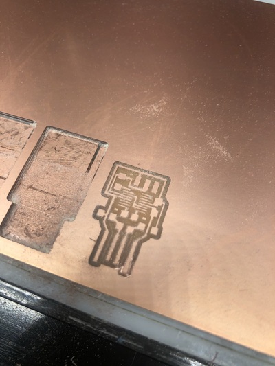
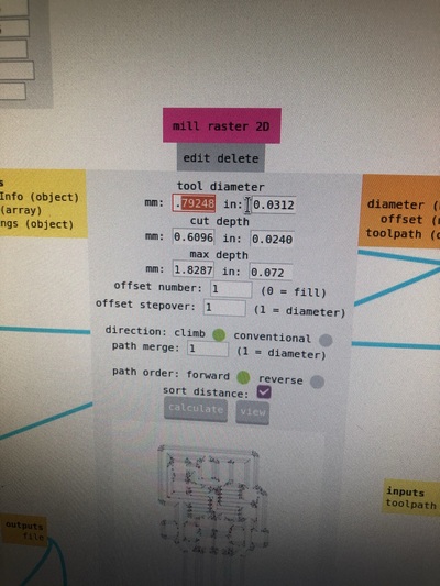
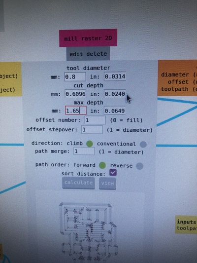
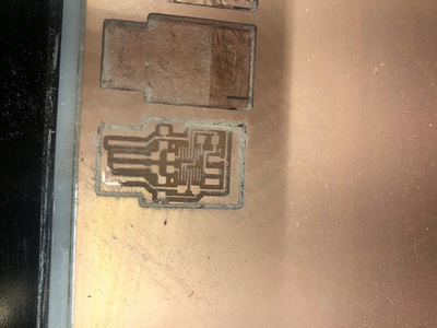
- Now for the cutout you need your other file and the .8mm milling bit and repeat the steps above; speed can be 4mm/s; cut depth is 1,55; .6mm per layer cut depth.
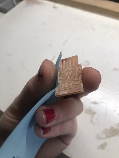
- Take the PCB out with with the screwdriver.
-
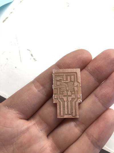
When the lines are rough you can sand them with regular paper
-
If you didn’t clear out the entire board, make sure to clear out the USB traces (I used a knife for this).
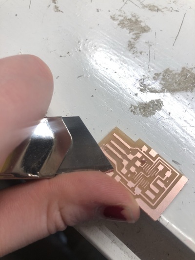
To stop the machine (not just pause it), you have to press the UP and DOWN for 10 seconds. The flashing lights indicate the memory is being erased. When it’s done, the lights stop blinking.
Soldering
- Clean the board with soap to get the grease out, wash it with water and dry it with a paper towel.
- The Weller Soldering station is 110V, starts at about 300 euros, about 40 euros per tip
- You can also get USB-C soldering irons and they’re really powerful (TS-80, about 60-80 euros, heats up very quickly, tips cost about 10 euros)
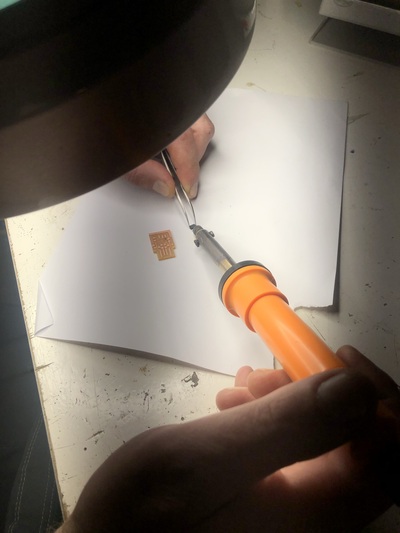
- ! Take one component at a time ! And put the boxes back immediately. Get the tweezers (electronics only, so the tips are not bent) and take them out carefully.
- Work from small parts to big parts and from the center to the outside, and don’t forget to consider the polarity of the parts!
- We still have the old solder with lead so it’s easier to solder (but worse for the environment than lead free solder)
- Surface mount: component is lying flat on the surface
- Soldering really small components using a USB microscope camera (basically a webcam) to see in great detail how the connections are (also great for debugging your soldering skills)
- If you have a component with very small legs that are close together, you can use a technique where you first add a lot of solder on top of the legs, then remove the excess of solder with a vacuum pump.
Steps:
- Put solder on the tip of the soldering iron so it’s shiny and smooth (clean first with the metal sponge)
- Put tip against the component and the trace to heat them up
- Add a little bit of solder and wait till it flows, then add a little bit more solder and let that flow too
- Remove the tip and you should have a smooth and shiny connection
- Clean the tip with the metal sponge again
It can also be helpful to add a bit of solder to the trace, then add the component, then bring back the soldering iron tip and add more solder.
When you remove the soldering iron too soon (or if you keep trying and fiddling), you get a cold solder joint and that won’t work well:
“A cold solder joint occurs when the solder does not melt completely. A result of insufficient heat, cold joints are often characterized by being rigid, rough, and uneven in appearance. This solder mistake creates an unreliable joint that is highly susceptible to cracking and failure.”
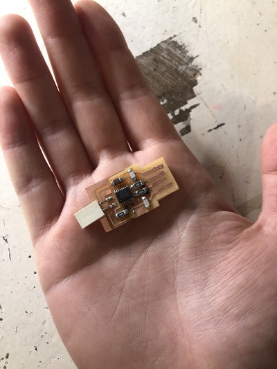
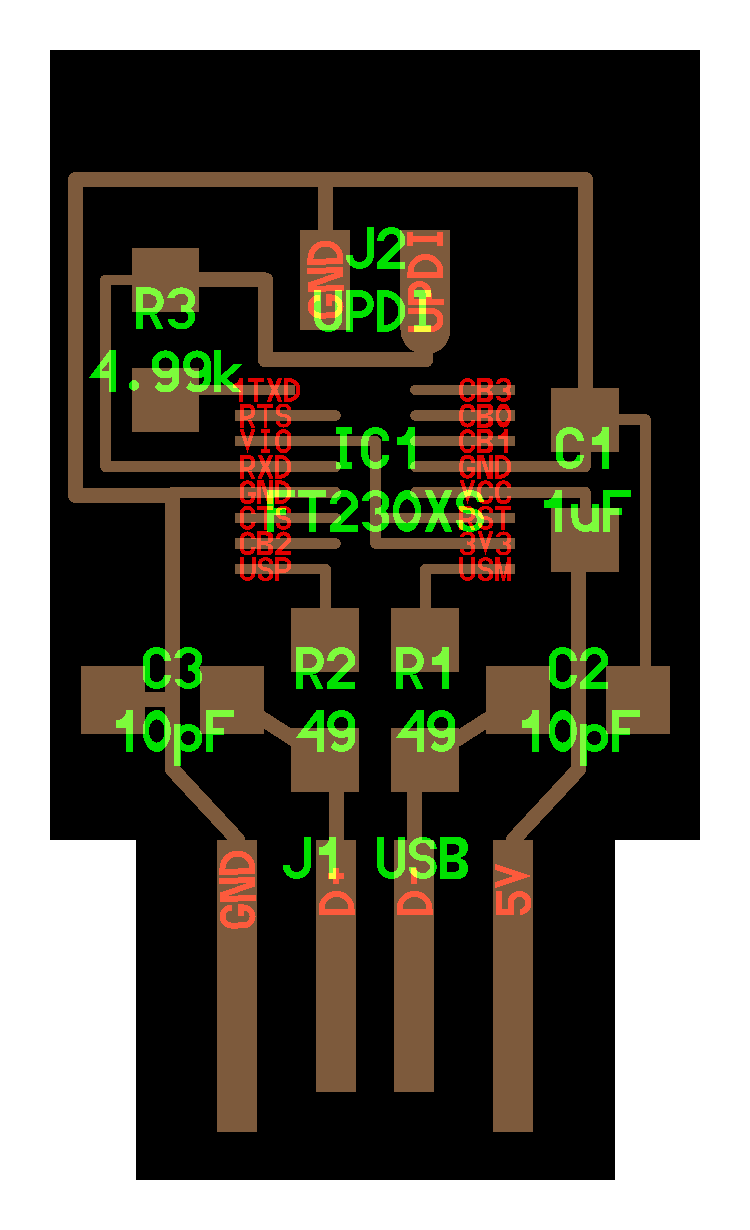
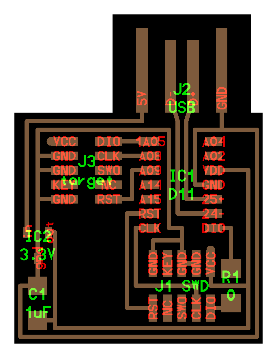
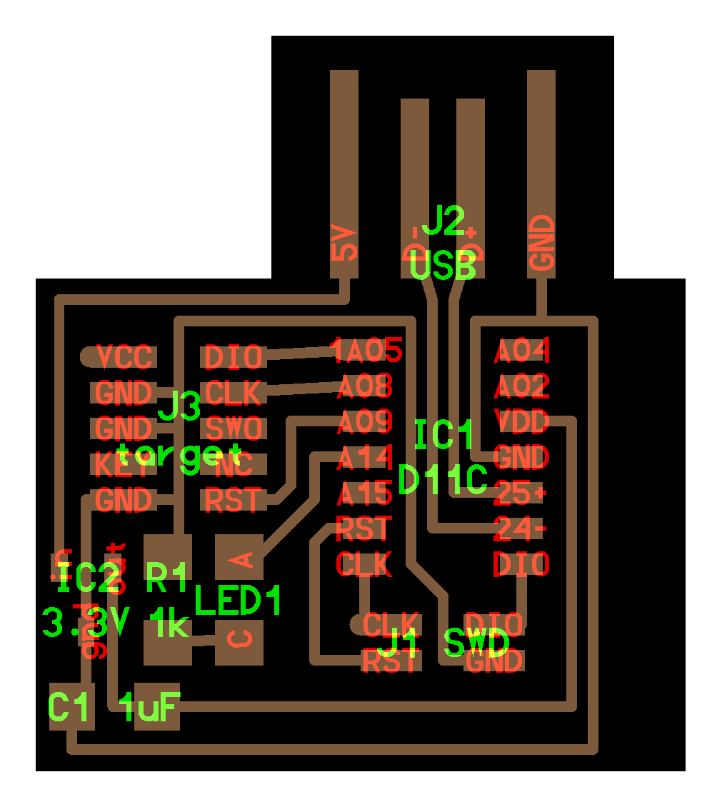
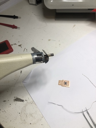
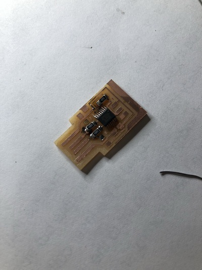
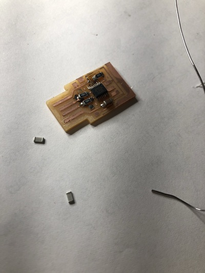
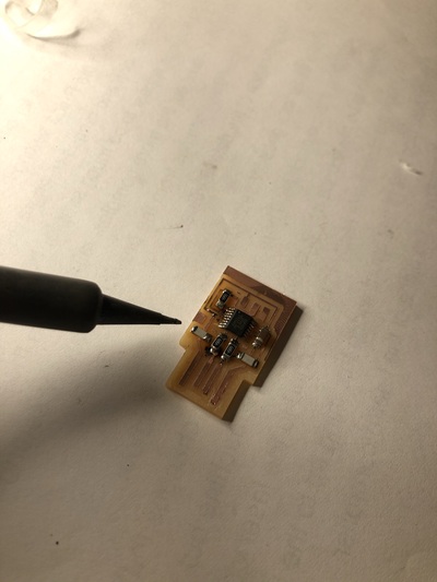
Documentation of the making of my own PCB programmer
UPDI
-
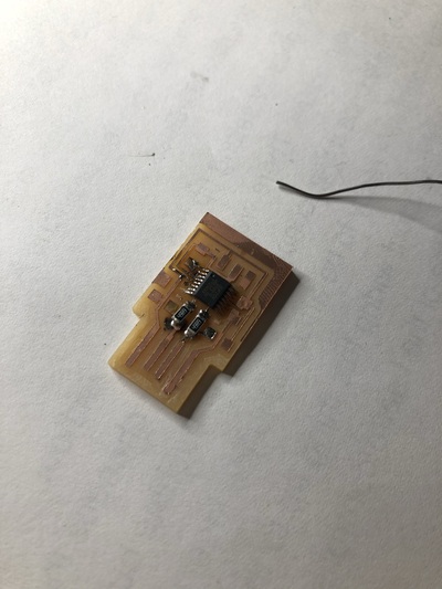
Soldering the chip (FT230XS microcontroller): since I messed it up Henk fixed it for me.
-
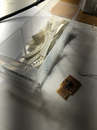
Soldering the resistors:
-
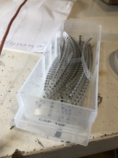
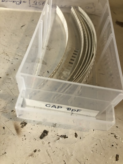
The capacitors (the capacitors we use are unpolarized so orientation doesn’t matter):
-
The J2 UPDI (Conn SMT 2WAY in the lab):
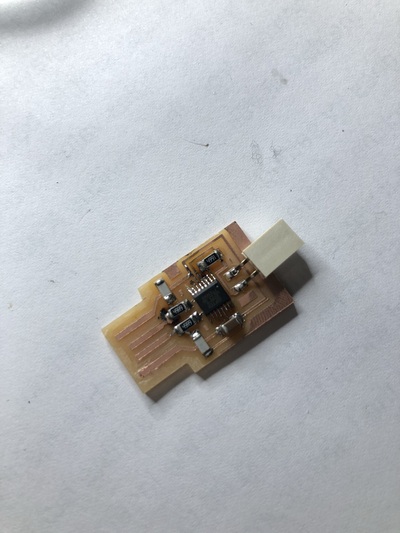
Final UPDI: